Total Time: 2.5 hours
Quick Links
- Introduction & Safety
- Fabrication Quest
- Software & Hardware for the Lab
- Part (0): Fusion360 Workspace
- Part (1): Sketching Objects and Dimensioning
- Part (2): Mirroring Sketch Geometries
- Part (3): Filletting
- Part (4): Linear Patterning
- Part (5): Importing DXF files
- Part (6): Remixing
- Part (7): Exporting DXF files
- Part (8): Laser Cutting
- Part (9): Assembly and Post-Processing
- Discussion & Reflections
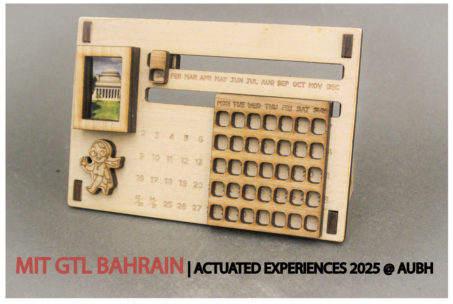
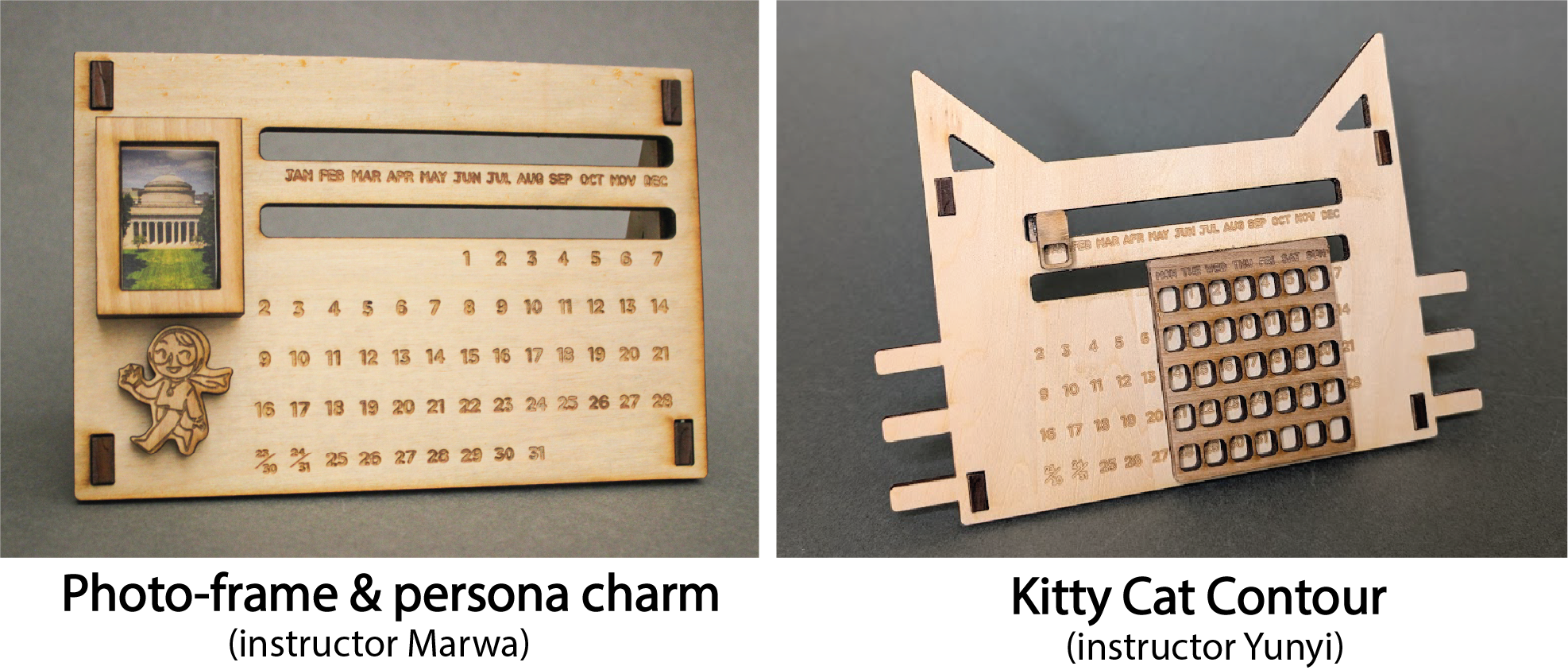
Lab 1: Let’s Laser-Cut a Calendar!
🦺 Introduction & Safety
(1 minute read)Laser cutting is a digital fabrication method that uses a laser to cut or “subtract” materials.
In this lab, you'll create a dynamic laser-cut calendar while learning how to:- ✅ Use Fusion360 for 2D CAD sketches
- ✅ Learn how to make a lasercut sliding mechanism
- ✅ Safely operate a laser cutter
- ✅ Post-process and assemble cut parts
Before we start, please make sure you understand the following safety precautions:
- Material Compatibility: Ensure that the material is laser-cuttable, has a thickness under 0.25" (6.35mm), and is cut with the correct power/speed settings.
- Fumes: Keep ventilation on and wait before opening the lid after cutting.
- Eye Protection: Monitor the process without staring directly at the laser.
- Emergencies: In case of fire, do not open the laser cutter lid, simply stop the machine and alert the shop manager immediately.
- Consultation: Always consult the D-Lab shop manager before cutting!
🔨 Fabrication Quest of the Day
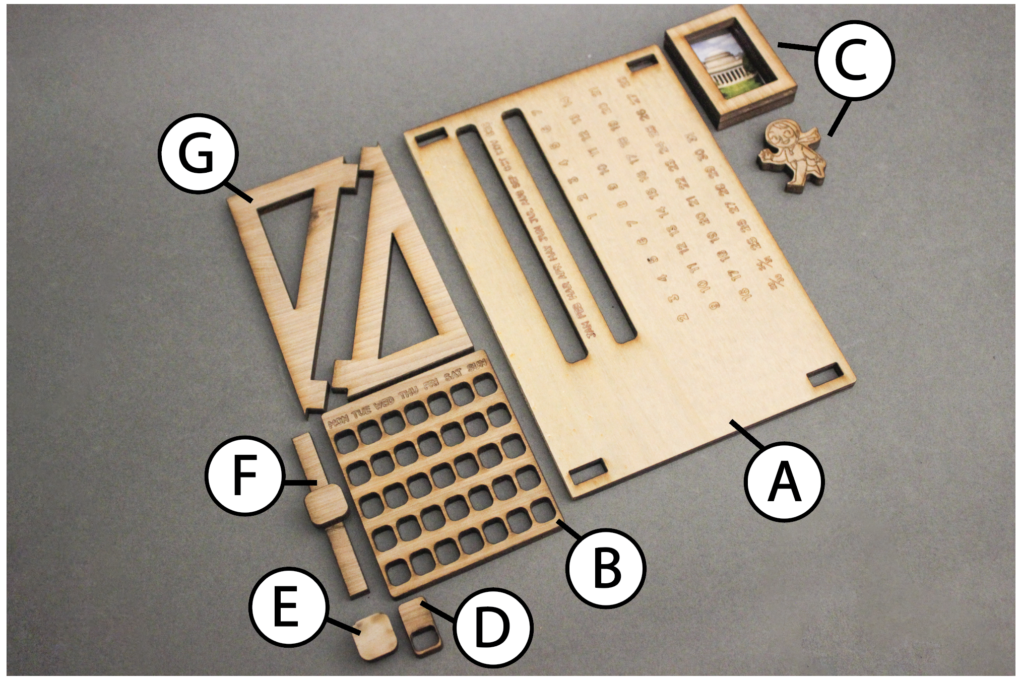
- Today, you will CAD 2 parts:
- (A) The rectangular calendar body (x1)
- (B) The day of the month slider (x1)
- And fabricate 1+ parts:
- (A) The rectangular calendar body (x1)
- (C) Your own “Remix” to the assignment
Remixing refers to you adding your own touch to a template so that it has your own creative touch to it. This will be a common theme throughout the labs.
Your instructors will provide you with the following:- (B) The day of the month slider (x1)
- (D) Day of the week slider (x1)
- (E) & (F) Slider stoppers (x2)
- (G) The triangular leg joints (x2)
🏗️ Software & Hardware
Software:
- Fusion360 (must download before workshop)
- Adobe Illustrator *Can download through Creative Cloud*
PPE:
- Safety goggles
- Face mask
- Nitrile gloves
Hardware:
Machines:
- Laser cutter
Part (0): Understanding Fusion360 Workspace (2 mins)
Watch the introductory video on the Fusion360 workspace and its basic tools.
Video Summary
- Top Panel: Save/open files and see current file names.
- Command Tools Panel: Solid, surface, and sketch tools are here.
- Side Panel: Shows document settings, created bodies, and sketches. You can rename objects, toggle visibility, and track the design hierarchy.
- Workspace: Where your sketches or bodies appear; control view angles.
- History Timeline: Tracks all design steps. You can adjust or delete steps by right-clicking. To enable, right-click "Document Settings" and select "Capture Design History."
Part (1): Sketching Objects and Dimensioning (20 mins)
[Parts 1-4 ONLY Covered in video]
- Create a New Design:
- Open Fusion360 and create a new design by going to File → New Design → Save. Name it "myDynamicCalendar".
- Choose a Plane for the Sketch:
- To begin sketching, we need to pick a plane or surface. In this case, we’ll use a plane.
- Orient yourself to the top view and click on the xy plane. Make sure the "origin" folder is toggled on so you can see the plane.
- Click the Sketch tool icon in the top panel. You’re now in sketch mode.
- Create the Main Rectangle:
- Select the Rectangle tool and click on the workspace to begin drawing. Place the first corner at the origin (the white dot).
- Drag the rectangle outward and click again to place the other corner. This point can be anywhere for now.
- Hit escape or done to stop drawing more rectangles.
- Dimension the Rectangle:
- Select the Dimension tool under Create → Sketch Dimension, or use the shortcut "D".
- Click on the width of the rectangle, drag downward, and click on the workspace. Assign it a value of 115 mm (ie, 11.5 cm).
- Repeat the process for the length, assigning it 170 mm (ie, 17 cm).
- Draw the Slider Holes:
[Part 5 ONLY Covered in video]
- Using the same steps as above, draw another rectangle inside the first one. This will be the hole for the slider.
- Dimension the new rectangle to 120 mm (length) and 8 mm (width).
- Now, dimension the vertical distance from the new rectangle to the main rectangle's top length to 20 mm.
- Dimension again the horizontal distance from the width of the slider hole to the width of the main rectangle to be 8mm (right-side).
- Repeat these steps, ensuring the vertical and horizontal distances are (vertical: 67 mm from bottom), (horizontal: 8mm from right) respectively.
- Add the Hole for the Triangular Base Finger Joint:
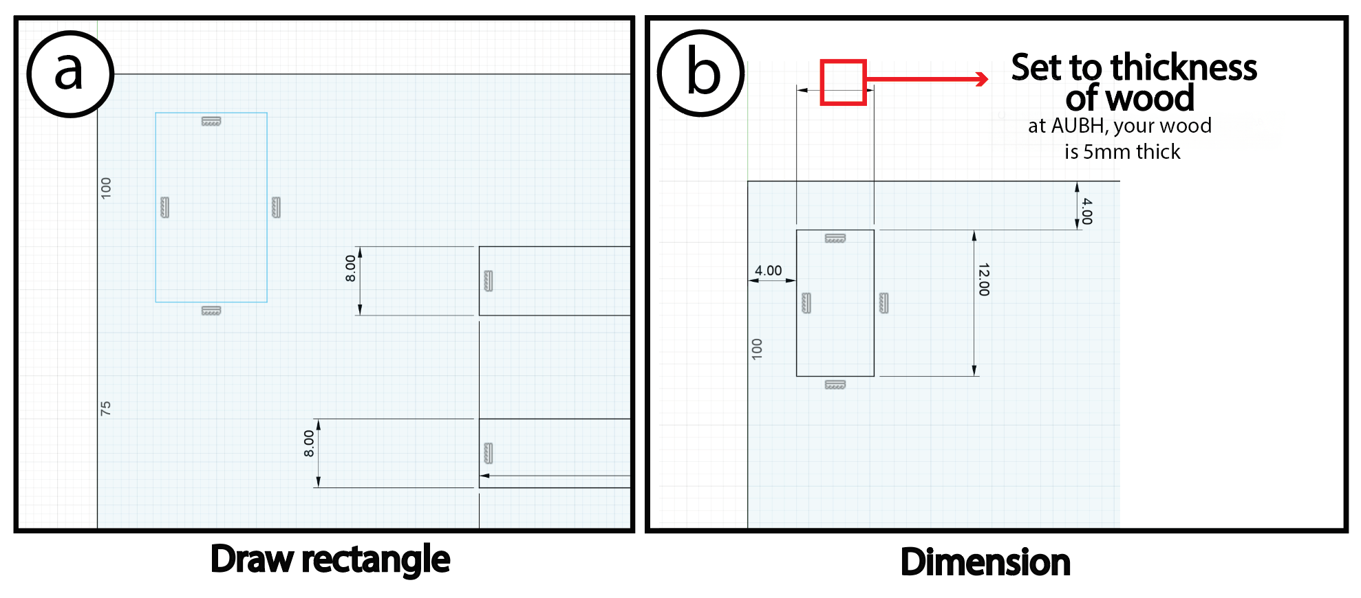
- To add the next hole, draw another rectangle like before and dimension it to 12mm (length) by 5mm which is the "thickness of wood" (width). Advanced Note: for a tight fit we will be offsetting by the "laser cutter kerf" in your lasercutter program (at AUBH, it is Lightburn). Also not that at MIT we used wood of thickness 6.35mm, which is what you might notice in the videos.
- Set the distance from the top of the hole rectangle to the main rectangle as 4 mm and from the left side to be 4 mm too.
- Quickly Duplicating Rectangles:
- We need three more rectangular holes, but instead of drawing them again, we’ll show a trick in the next section to quickly create multiple rectangles. This method saves time, especially if you have many shapes to duplicate.
Part (2): Mirroring Sketch Geometries (10 minutes)
To save time, let’s mirror the rectangle instead of creating it again. Mirroring works by reflecting shapes about a line or plane, similar to how you learned in school with x,y and z axes.
- Create a Mirror Line:
- Select the Line tool, but don’t click done or anywhere on the workspace yet.
- On the side panel, choose Construction Line. This type of line is not part of the model itself, it’s used purely for construction purposes.
- Position the Line:
- Hover over the length of the rectangle until you see a small triangle appear—this marks the midpoint of the rectangle’s length.
- Click on the midpoint and drag your mouse to the opposite side of the rectangle. Ensure you also see the triangle (indicating midpoint) and a symbol indicating the line is perpendicular to the rectangle width.
- Now you've created a construction line that we can mirror the rectangle across!
Checkoff 2
Show your instructor that you have constructed a mirroring lineNow, let's create a horizontal construction line across the rectangle’s width:
- Create a Horizontal Line:
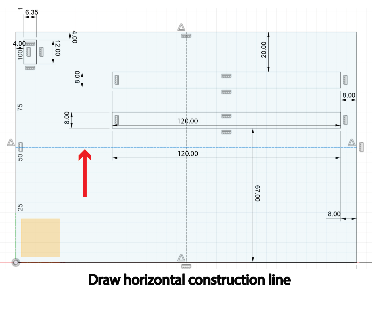
- Repeat the previous steps to draw a line, but this time horizontally.
- Start and end the line at the midpoints of the rectangle’s width. Remember, it’s a construction line!
- Mirror the Rectangular Hole:
- Go to the mirror tool (under Create → Mirror).
- In the pop-up, select the rectangular hole you made as the object to mirror.
- Choose the vertical construction line as the mirror line.
- Congratulations, you’ve mirrored the part and have two holes!
- Mirror Again:
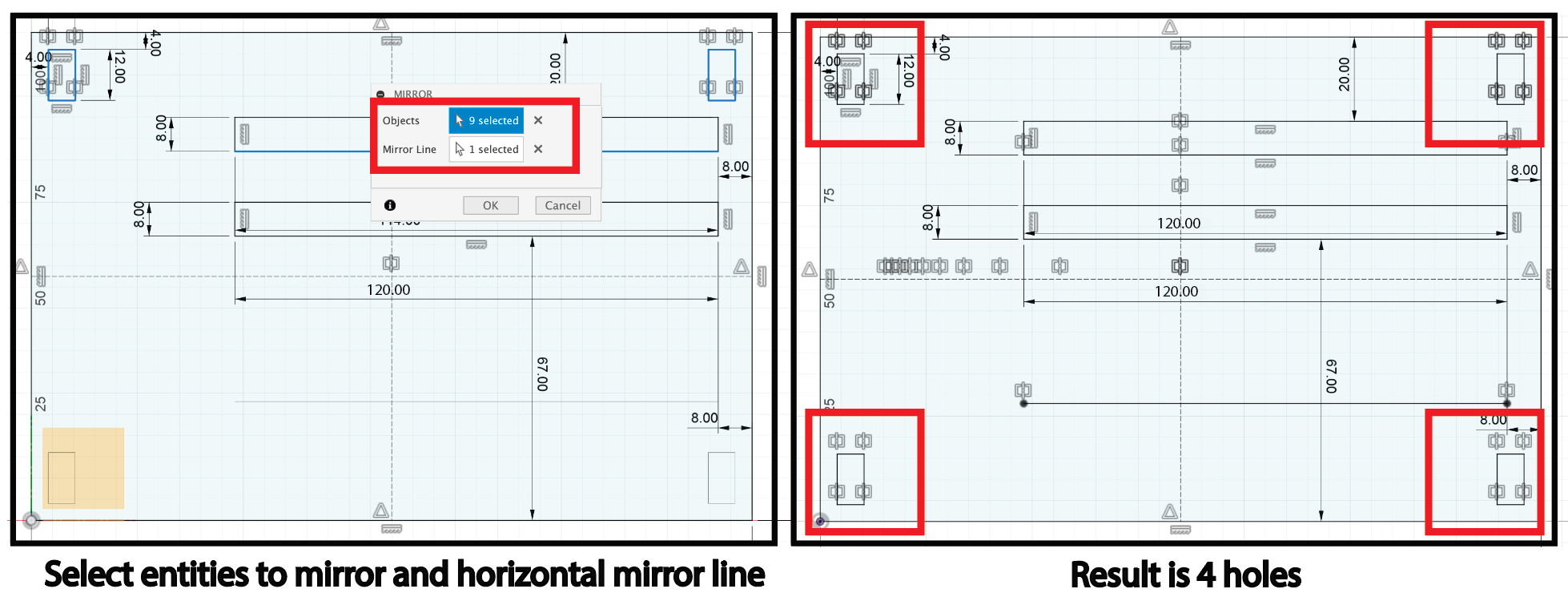
- Repeat the mirroring process, but this time use the horizontal construction line to mirror both holes.
- All your four holes are now complete!
Part (3): Filletting (5 minutes)
Filleting is the process of rounding off sharp edges on your design. For laser cutting, filleting is important because sharp corners can create stress points in the material, which may lead to cracks or breakage. Filleting smooths out those corners, improving durability and aesthetics.
Now your design is filleted and ready for a cleaner, more durable laser cut!
Part (4): Linear Patterning (10 minutes)
Next, let's design the small day-of-the-month slider:
- Draw the Outer Rectangle:
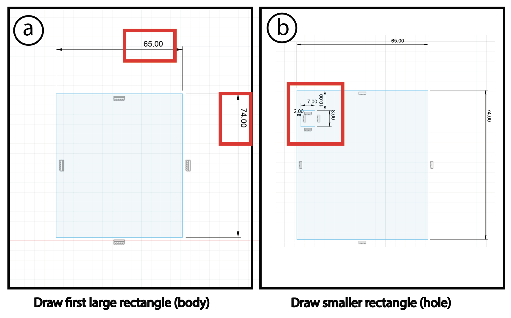
- Similar to Part(1), draw a rectangle. Dimension it to 74mm by 65mm, and make sure it’s not overlapping the previous design's main.
- Create a Smaller Rectangle Inside:
- Inside this rectangle, draw a smaller one representing the holes for days of the month. Dimension it to 7mm by 8mm.
- Place this smaller rectangle 10 mm from the top and 2 mm from the side (left).
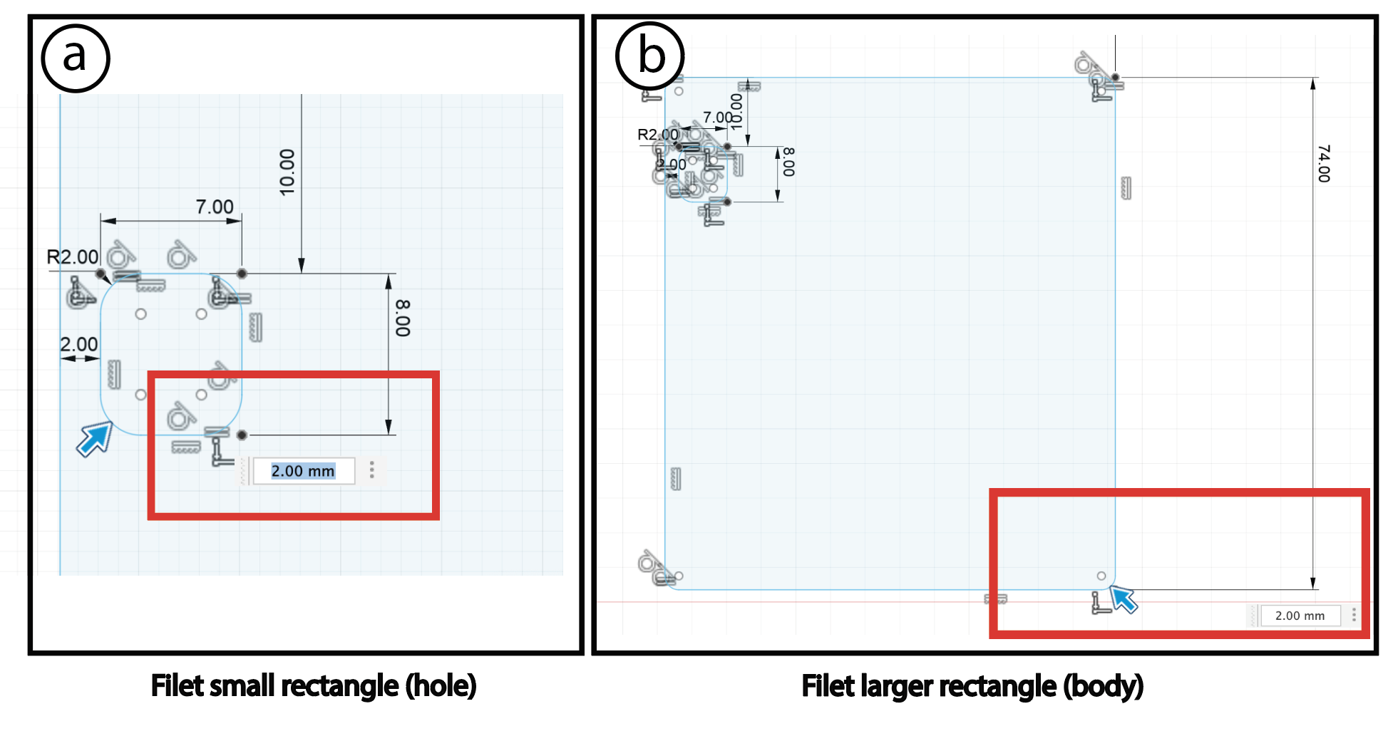
- Fillet the Rectangles:
- Input the fillet radius as 2 mm.
Now that we have filleted our rectangles, let’s create the remaining rectangles.
- Adding Multiple Rectangles:
- Instead of creating X more rectangles manually, let’s use linear patterning.
- What is Linear Patterning?
- Linear patterning replicates an object along a straight line, horizontally, vertically, or both. It’s a shortcut to avoid repetitive work.
- Use the Linear Pattern Tool:
- Select the part you just made.
- For the horizontal patterning, set spacing to 9 mm and the number of copies to 7.
- For the vertical patterning, set spacing to 13 mm and the number to 5.
- Reflect:
- Why don’t we use mirroring here?
Part (5): Importing DXF File (5 minutes)
We need to add text to our calendar, so let’s import a DXF file.
Download DXF file from hereWhat is a DXF?
A DXF (Drawing Exchange Format) is a vector file format used for 2D designs, allowing you to import elements like text from software like Illustrator into Fusion360.
- Click Insert → Insert DXF in Fusion360.
- Select a Plane: You'll need to choose a plane to import the DXF onto. Select the XY plane.
- Move the text to the desired position in the workspace by dragging it (here, move to X:-2.5mm, Y:-103mm)-- you may adjust this a bit in Illustrator later if it feels too close to the slider edge aesthetically
- Now, you’ve imported the text! You can always design in external software (like Illustrator) and bring it into Fusion360 as a DXF file to further manipulate-- this will be helpful later on if you want to add logos for 3D printing, for example.
Part (6): 🚨Remixing🚨 (30 minutes)
Now it's time to “remix” this assignment by adding your own flair! Be creative and think about how you can personalize your design. If there's anything specific you want to create but aren't sure how, let us know so we can guide you!
Checkoff 7
Show your remix to your instructorPart (7): Exporting DXF file (5 minutes)
- Export the Sketch:
- Right-click on your sketch.
- Select Export as DXF.
- Open the DXF File:
- Open the exported DXF file in Adobe Illustrator (set the import to 1 unit = 1mm -- make sure units are in mm).
- Remove Construction Lines:
- Delete the lines that correspond to the construction lines included in the export.
Note: In future labs, we’ll demonstrate a method to export without including construction lines, which will streamline your workflow!
Checkoff 8
Show the exported file to your instructor to start lasercuttingPart (8): Lasercutting (30 minutes)
For this part, please follow your instructors to D-Lab in order to lasercut; We will use Adobe Illustrator as our choice of Vector editing file that we can open our DXF in it, and interface with the lasercutter.
Your instructors will demonstrate to you what vector vs. raster files are, and how to set-up files for lasercutting. You may skip reading this scetion and just head to D-Lab. 😎
For your future reference, we will provide some insructions below on how to create an image for "vector cutting" vs. "rastering/engraving":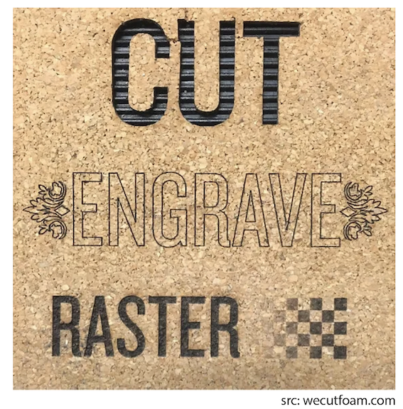
- Vector Cutting: The laser follows a path to cut through material (subtracts material).
- Engraving: The laser etches or marks the surface without cutting through (usually like an outline).
- Rastering: The laser scans and etches (no cutting) in a grid pattern to create detailed images or shading on the surface (great for photos and textures).
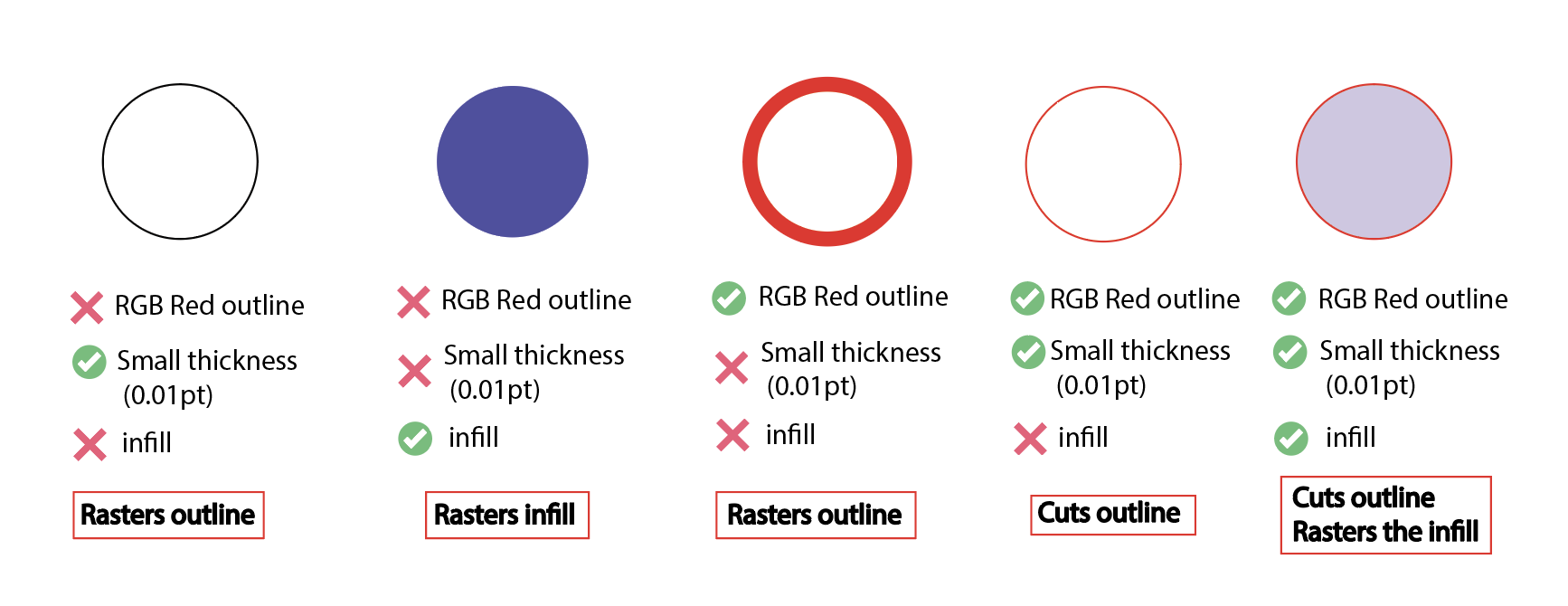
- Vector Cutting:
- Raster Engraving: Anything that does not meet vector requirements
Part (9): Assemble the Calendar and Sand the Edges (30 minutes)
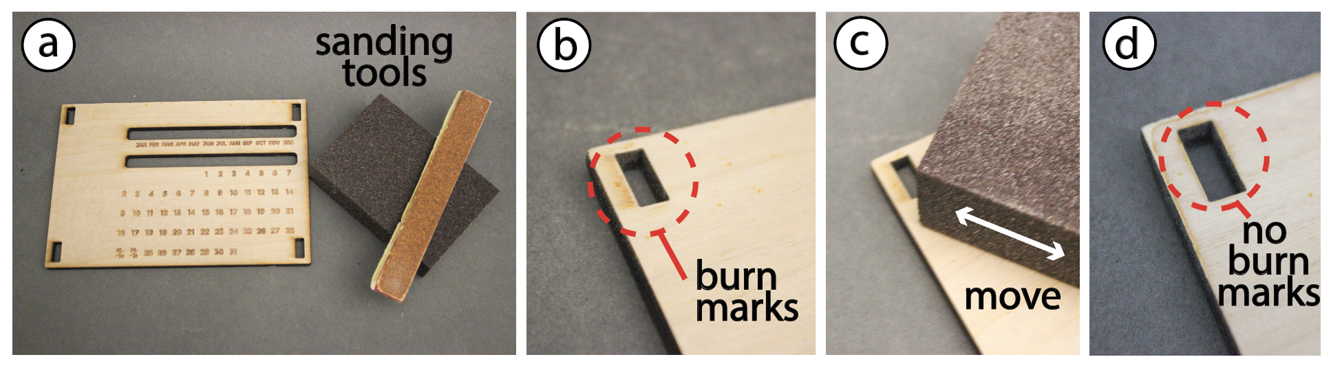
- Sanding Surface:
- Follow the visual instructions from the figure to sand off the burn marks on your piece.
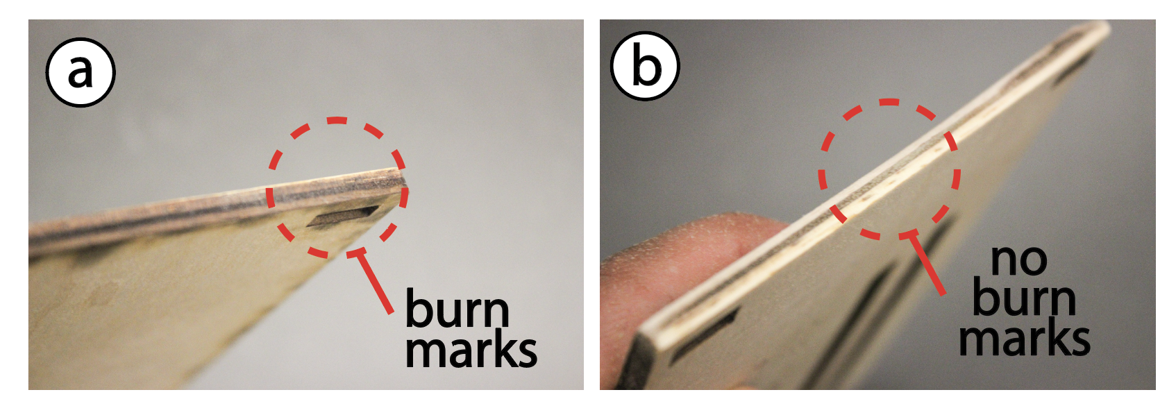
- Sanding Edges:
- Repeat the same process but with the edges
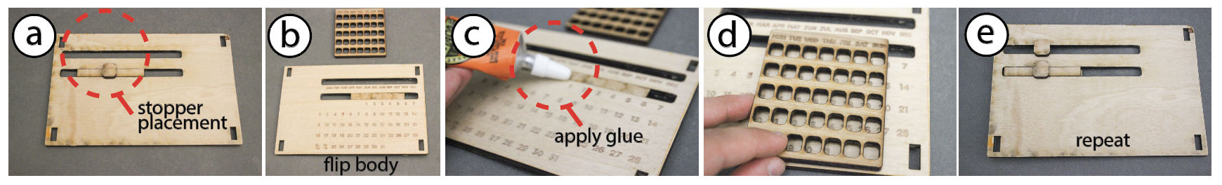
- Insert the Sliding Mechanism:
- Flip the calendar so that you are facing the back. Begin by inserting the long rectangular stopper component in the slot for the day of the month into its designated slot as shown in figure (a) (above).
- Glue the Stoppers:
- Flip the calendar so you are facing its front now. Glue the day of the week slider and place it on top of the stopper(c-d). Make sure to hold in position until the glue sets (15 minutes dry time).
- Repeat:
- Repeat previous steps for the month slider.
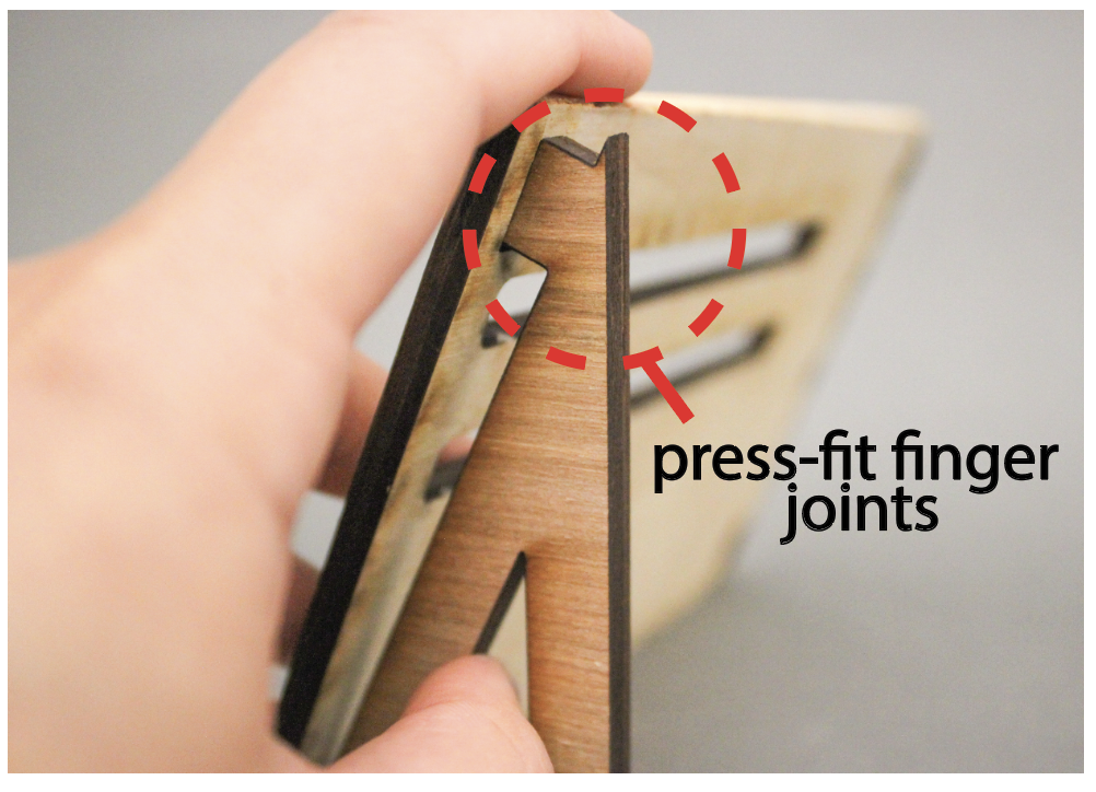
- Assemble the Legs :
- Once the glue has dried, press-fit the legs into their corresponding holes to secure them in place.
- Final Assembly:
- If you created any remix pieces, assemble those as well.
Congratulations, your dynamic calendar is ready! 🎉
Discussion & Reflections
- Discuss the advantages and limitations of using laser cutting for digital fabrication.
- What can we make? What is difficult to make?
- Reflect on the design process
- Consider any modifications that you would like to implement to improve/elevate your designed remix.
- Further Readings