Total Time: 1 hour and 45 mins
Quick Links
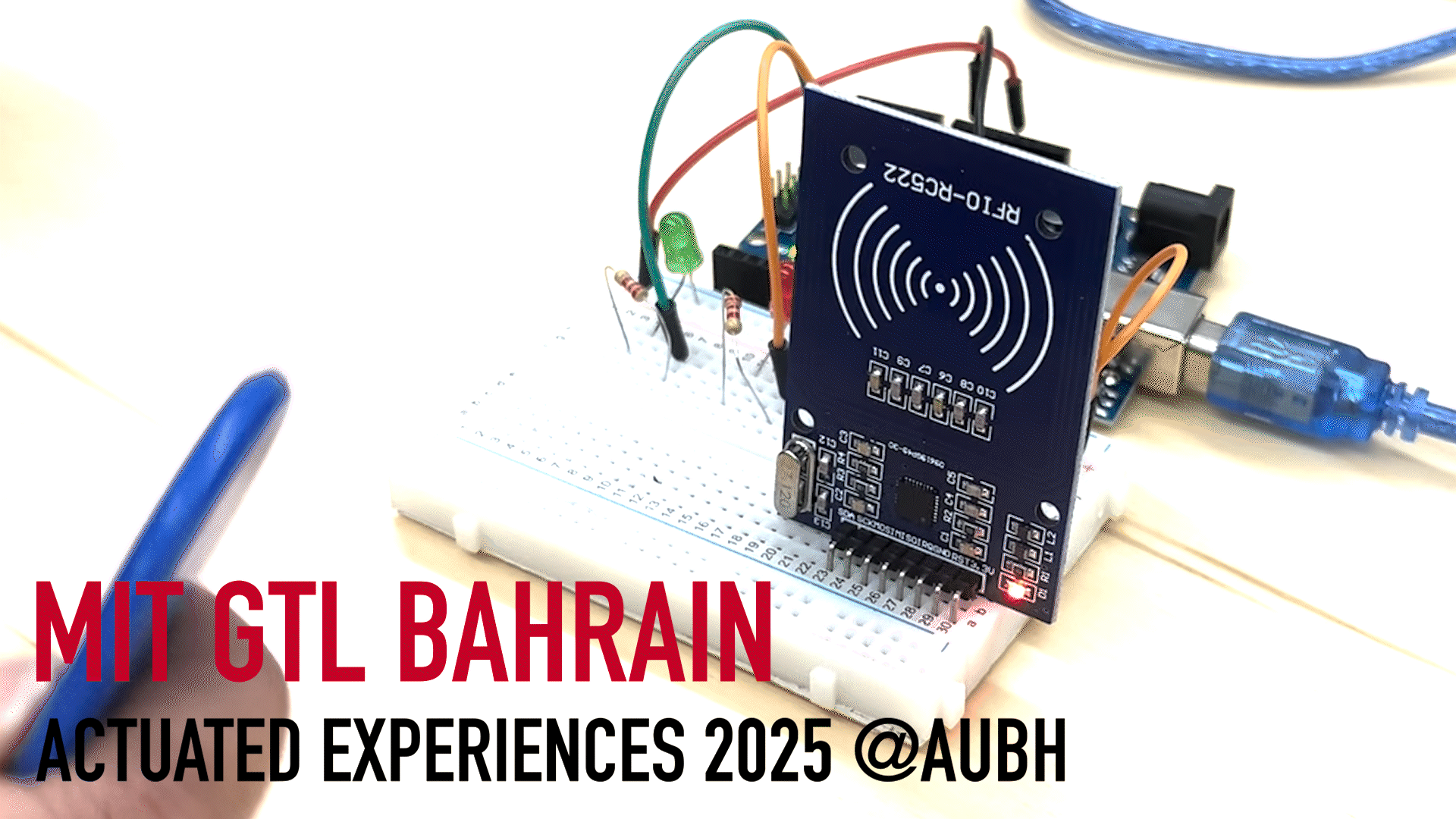
Lab 6: Circuits, Breadboards, Inputs & Outputs!
🦺 Introduction & Safety
(1 minute read)This is an introduction to interfacing with the electrical world and code to really make your projects come to life!
In this lab, you'll create a RFID reader that grants access depending on your ID while learning how to:- ✅ Code in Arduino
- ✅ Learn how to wire and understand basic electronics
- ✅ Wire a peripheral (the RFID chip)
⚠️ Before we start ⚠️, please make sure you understand the following safety precautions:
- High Current: Never connect power and ground directly with a wire. High currents are very dangerous.
- Wiring with Power Off: Whenever wiring on your breadboard, please disconnect the Arduino wire from the computer so that the power is off.
🔨 Fabrication Quest of the Day
- Today, you will make a LED blink:
- (A) Breadboard with a Circuit! (x1)
- And wire an RFID reader!
🏗️ Software & Hardware
Software:
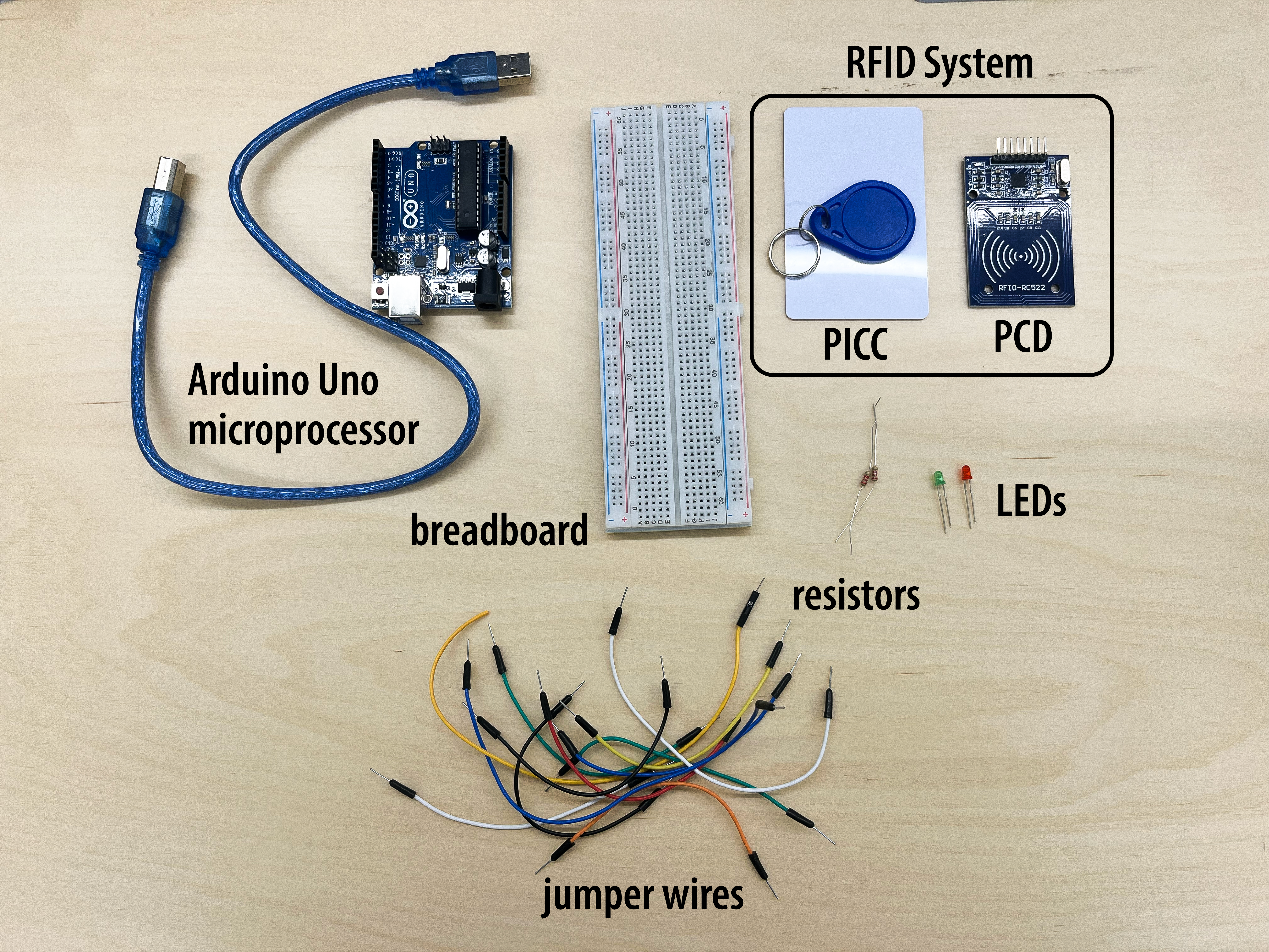
Hardware:
- Breadboard
- Jumper Wires
- Wire Cutter
- LEDs
- Resistors
- Arduino Uno
- Multimeter
- Laptop
- RC522 Chip Module
Part (0): Hello World, Arduino! (15 min)
Today, we will be working with Arduino, a microcontroller. A microcontroller is basically a very small computer chip that can interface with the real world using voltages. Arduino is just a user-friendly and widely used microcontroller.
Our first step is downloading the software, Arduino IDE. Arduino is the physical microcontroller and the IDE is the code software. Navigate to this link.
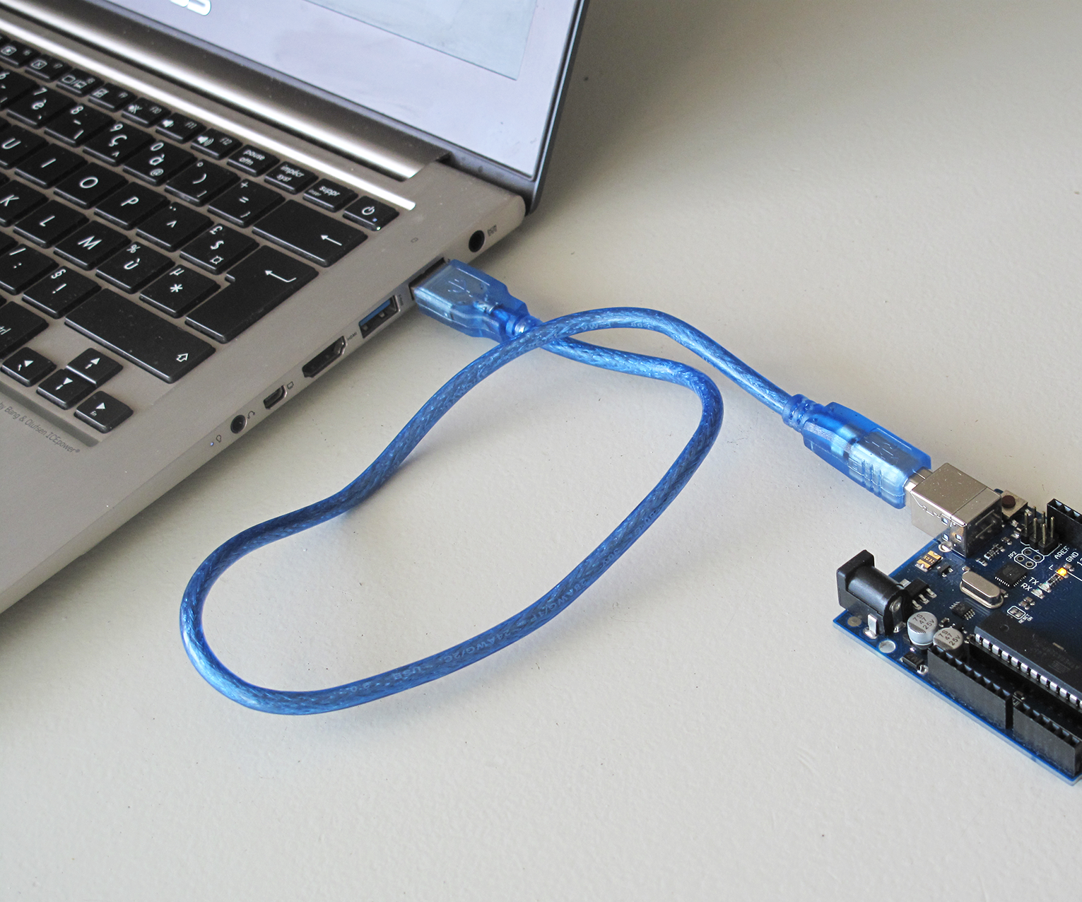
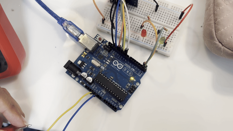
Then, we need to physically plug in the Arduino Uno into the laptop like this:
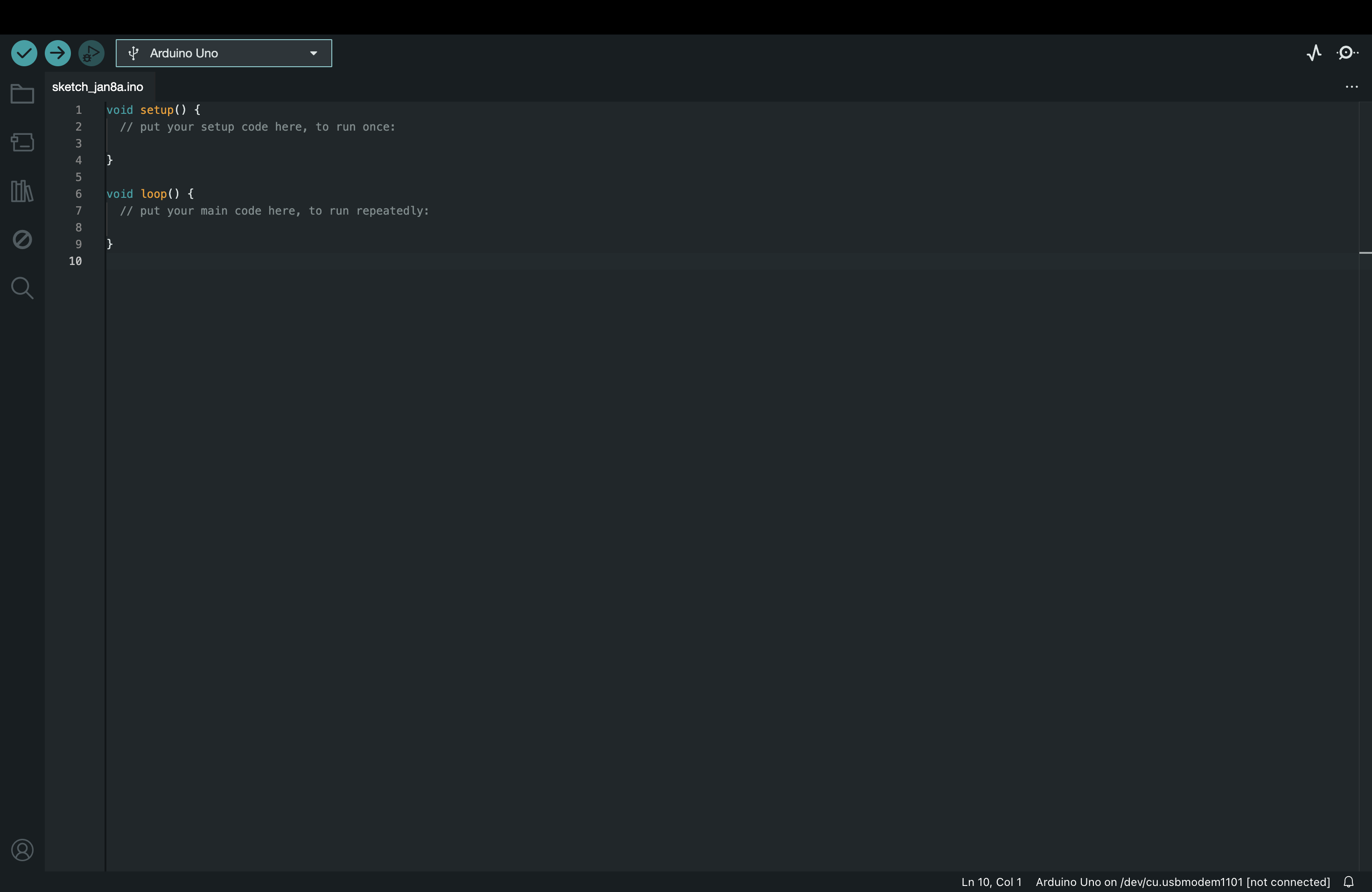
Now, we can try to open the Arduino IDE program. You should be greeted by a window that looks like this:
Mine happened to automatically connect to the Arduino Uno. However, to double check that the device was configured, navigate to Tools > Port > Arduino Uno and make sure that is the Arduino Uno. You should get something like this:
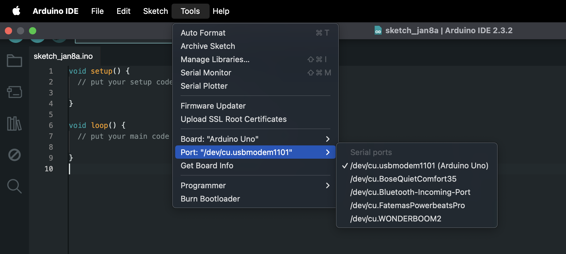
Let's also click Tools > Serial Monitor. A terminal at the bottom of your window will appear.
The Serial Monitor
is a print window which you can output information. This a great tool to make sure your code is working correctly,
a term called debugging. We will come back to the terminal once we start running our code.
Now, we will try to understand the basic structure of Arduino code which is in the C programming language. The program is divided into setup() and loop(). The code inside setup is ran once when the Arduino is first powered while the code inside loop is ran repeatedly after the setup. Let's take a deeper look into a code block.
// this is a comment
void setup() { // this is an in-line comment
    Serial.begin(9600); // this is code that opens the Serial port and 9600 bits per second
}
When you see parenthesis after some text, it is typically a function . So, setup() , loop() , and begin() are
all functions. A function is a block of code. The parenthesis can be empty like setup() and loop() or have an input.
begin(9600) for instance has an input of 9600.
In the above code, we are defining what is inside setup(), hence the curly braces.
The void at the beginning means are returning nothing at the end of the function. Then, inside of the {} is the body of the code.
Each line of code in the body must end in a ;. Lines that begin with a // are comments which are instructions that are just for
human readability and not read by the machine. Type the above code into your window. Let's move to the loop function.
// there are two functions in Arduino: setup and loop
// setup runs only once
void setup() {
    Serial.begin(9600); // open the serial port at 9600 bps:
}

// loop runs over and over
void loop() {
    Serial.println("Hello World!");  // prints to the Serial Monitor and makes a new line
    delay(1000);    // sleeps the program for 1000 ms (1 second)
}
Now, type the above code into your code window. This will print "Hello World!" into your Serial Monitor every second. Try clicking the run button (the circle with the arrow at the top of the window). You should see something printing now! Congrats on *maybe* your first Arduino program!
Part (1): Breadboarding Basics and Multimeters (25 mins)
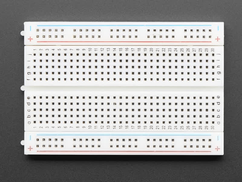
The goal of this section is to make a LED blink. However, we need to lay our circuit on something like a breadboard. A breadboard is basically like a preliminary construction board for making circuits! The areas highlighted in green are the parts that are electrically connected to each other. The holes allow you to stick wires inside.
Normal Breadboard:
Internal Wiring of Breadboard:
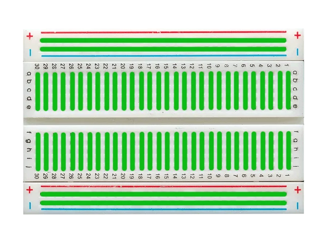
💡 Typically, you put the ground line on the blue minus rail (➖) and the power on the red plus rail (➕). This way, you can easily grab those connections.
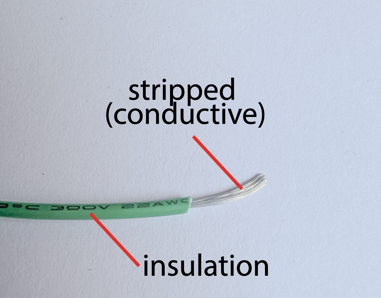
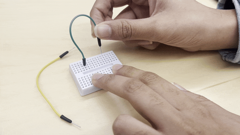
We want to introduce you to some other tools, too. How do we get wire to connect components? We can use a wire stripper and get it from a spool of wire. In the image below, you can see the stripper. There are different-sized holes representing the gauge of the wire.
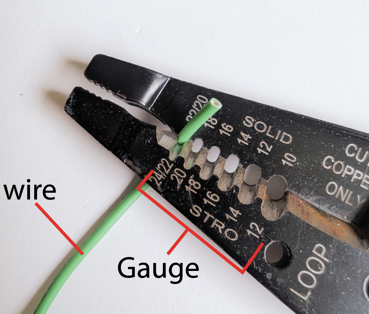
In the image above, using the hole makes an incision on only the insulation, and then you pull the insulation off to only expose the metal on a portion of the wire. To cut the wire, you clamp the wire on the section where it says cut on the strippers (the bottom portion of the sharp edge). You should get something like this:
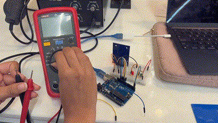
To test connections, there is another tool for measuring: the multimeter. It has features like testing voltage, current, connection, etc. The orientations of the symbols change from multimeter to multimeter, but the symbols are what stay consistent. We will note the ones that matter for this lab and future labs here.

The V with a dotted and straight lines above it measures DC voltage. DC, or direct current, is basically signals not changing consistently or very often. The ohm symbol, Ω, stands for measuring resistance. The WiFi looking signal with the curved lines in series is continuity mode. It beeps 🔉 when there is an electrical connection between the positive and negative terminals of the multimeter. Try testing each of these modes and be prepared to show them off during checkoff.
Measuring Voltage:
Measuring Resistance:
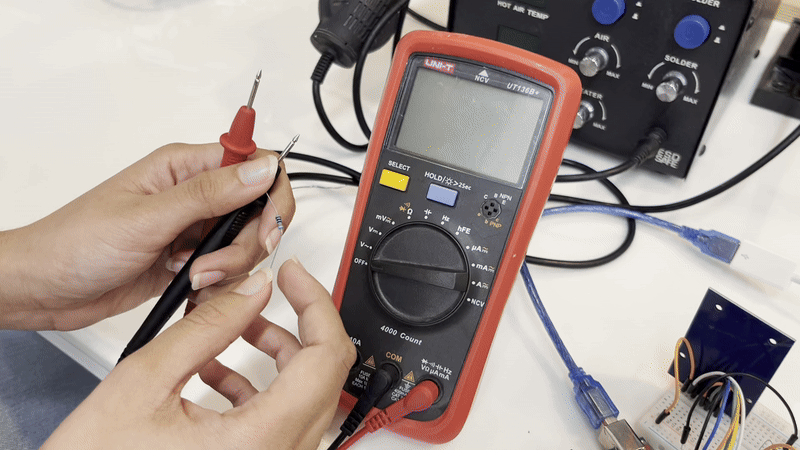
Continuity Mode:
Now, this is the schematic we will build in the next section:
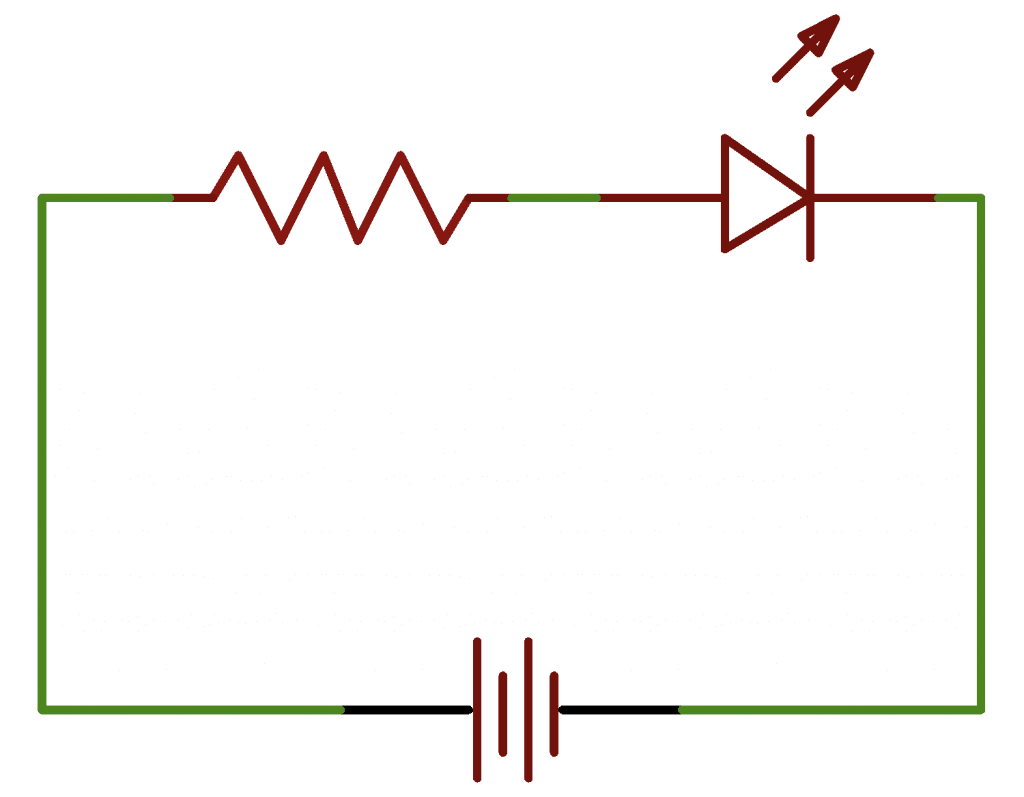
However, we will not tell you what resistor value to use. Using V=IR, we will ask you to figure out what resistor to use. Note that the Arduino supplies 3.3 V. For current, let's try to get between 10-15 mA.
Checkoff 1
Show your instructor your calculations and your multimeter skills! Your instructor will also bring a wire and wire stripper to briefly practice wire stripping. You do not need to build your circuit in this section.Part (2): Making a LED Blink on Your Breadboard (20 minutes)
⚠️ Again, whenever wiring on your breadboard, please disconnect the Arduino wire from the computer so that the power is OFF. Let's go over the compoents and how to to insert components.
Since we have limited wire strippers and limited time, let's just use jumper wires. These are just pre-cut wires that you can insert immediately into the breadboard.
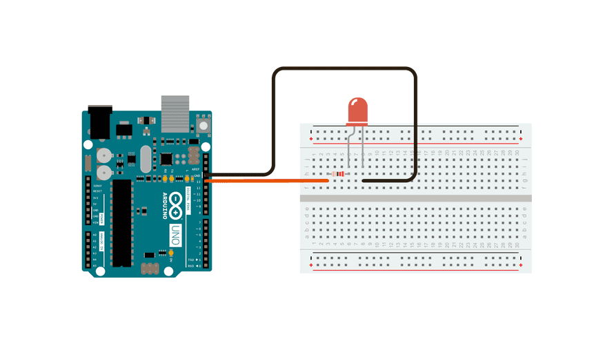
Refer to the breadboard image in Part (1) to understand the green lines we're talking about. When you want to insert a resistor, you do not want to put both legs in the same row (same green region). You want to put it in a different row (a different green line). This is because the first method shorts it. Current would simply never flow into it since it wants to go the path of least resistance. The image below is a valid way of inserting a resistor. The resistor's legs are in two different rows. This is a diagram of what you will build:
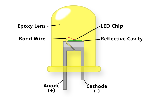
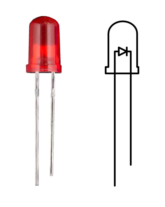
An LED has two diffent legs. The shorter leg of the LED should be connected to ground. Anode is the positive end of the LED (longer leg) while cathode is the other leg.
Now, you're ready to start making your full circuit on the breadboard. We will use pin 11 as our output pin (the positive terminal).
After you have built the circuit physically, it is time to code again. We will be introducing two new functions: pinMode() and digitaWrite(). pinMode() sets a pin of the Arduino to some mode. We make it OUPUT mode so that we can "write" to it and set it to voltages. To write to a pin, we use the digitalWrite() to assign a voltage to a pin. To make the LED blink, replace the code in the code editor with this code:
// there are two functions in Arduino: setup and loop
// setup runs only once
void setup() {
    pinMode(11, OUTPUT); // this makes pin 11 an output
}

// loop runs over and over
void loop() {
  // turn the LED on (HIGH is the voltage level)
  digitalWrite(11, HIGH);
  delay(1000); // Wait for 1000 millisecond(s)
  // turn the LED off by making the voltage LOW
  digitalWrite(11, LOW);
  delay(1000); // Wait for 1000 millisecond(s)
}
You should have a 💡blinking LED💡 now!
Checkoff 2
Show your instructor that you have a blinking LED!Part (3): Wiring RFID (20 mins)
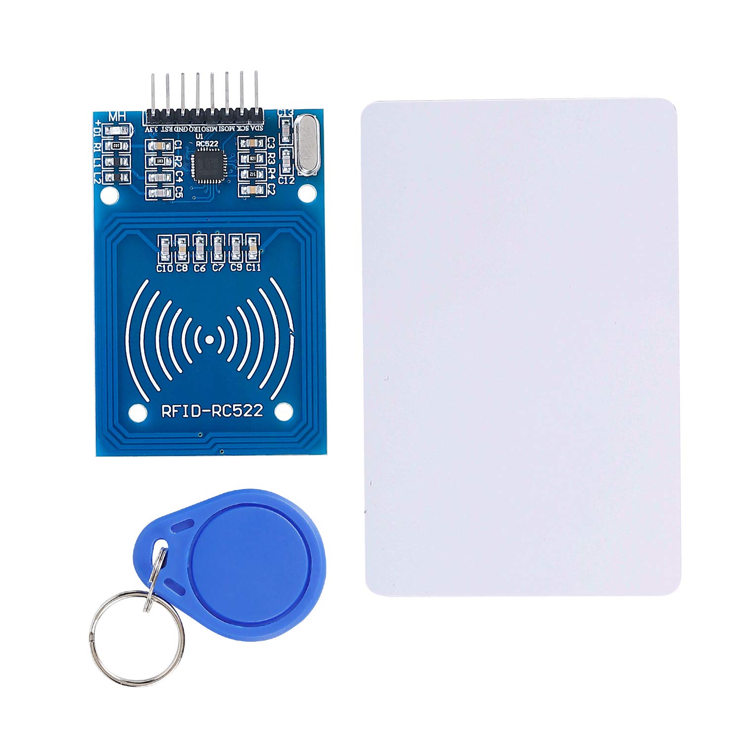
As mentioned in lecture, Radio Frequency Identification (RFID) is a universal security system. There are three main components of RFID: the PICC (your card), the PCD (the reader), and the computer (the Arduino). RFID is very difficult to make from scratch. So, we will use some help. The RC522 chip module does a lot of the processing for us and will act us a reader.
🚧 Deconstruct the LED circuit before wiring the RFID chip. Now, we need to wire the RFID chip to the Arduino. This will require quite a few wires. Try to plan your wiring to be as neat as possible. Use the jumper wires to make the connections. Here is a diagram and table of the connections.
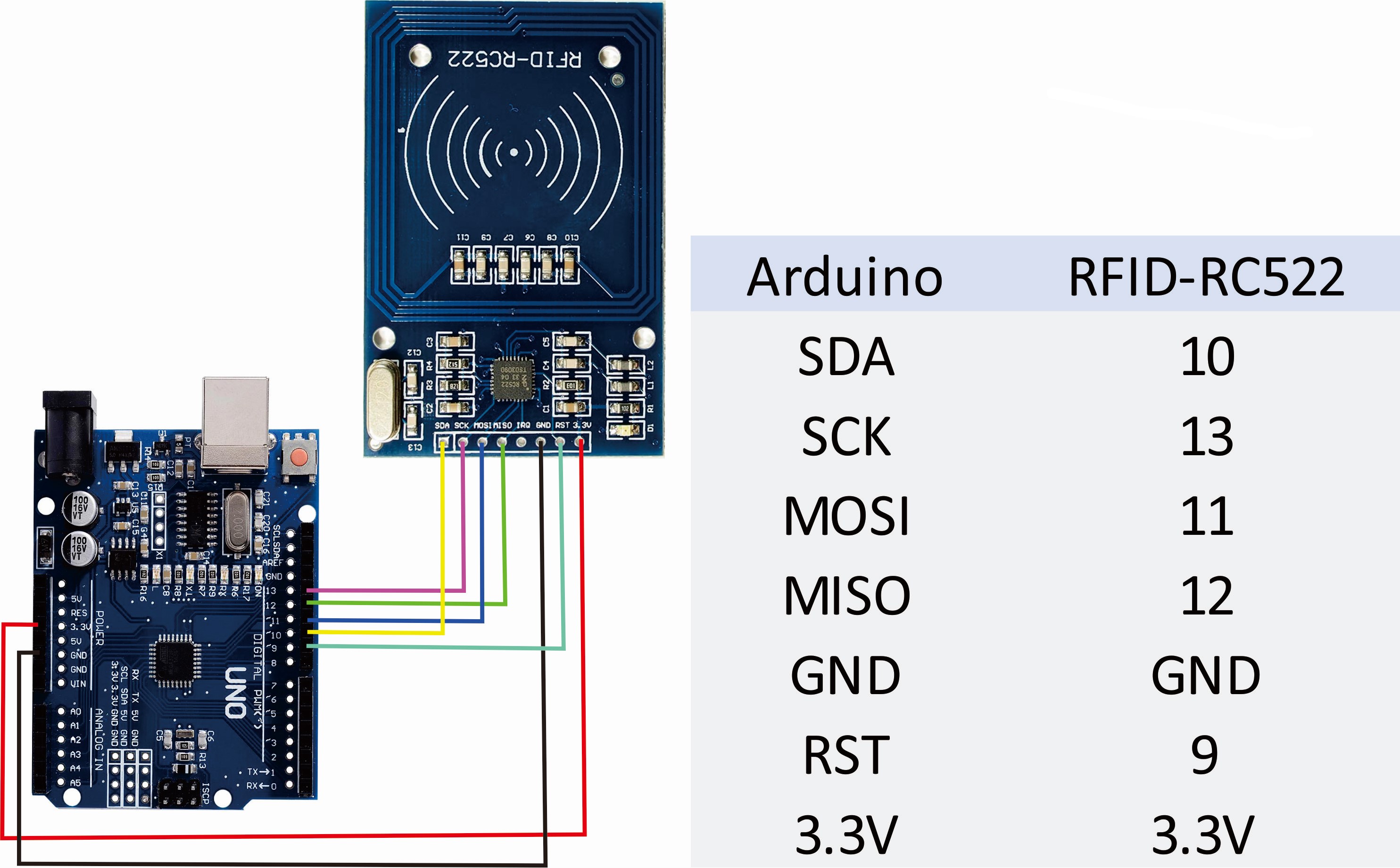
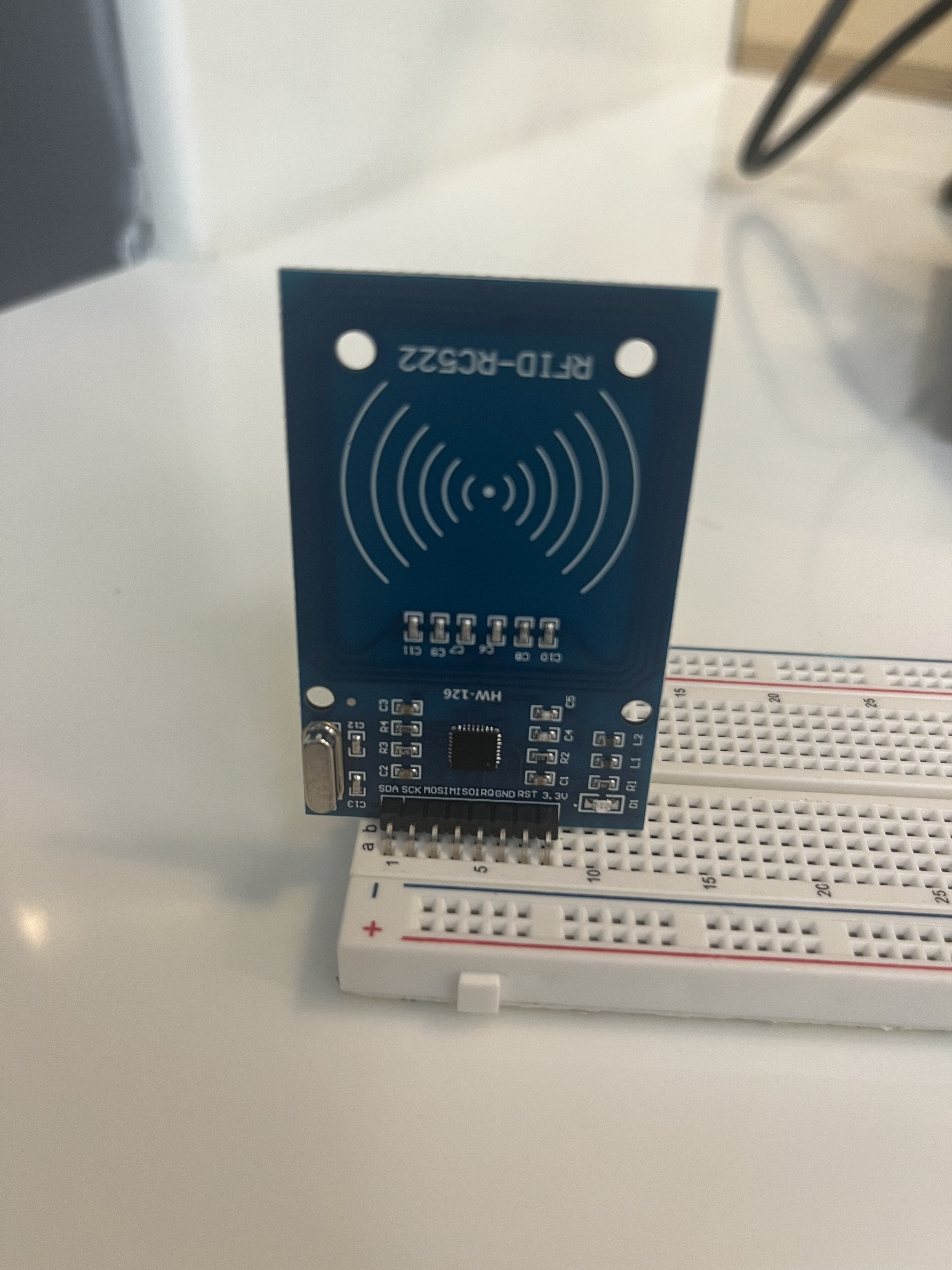
We need to connect the RC522 to our Arduino to communicate to it. We slot it into our breadboard like this such that the reader is facing out:
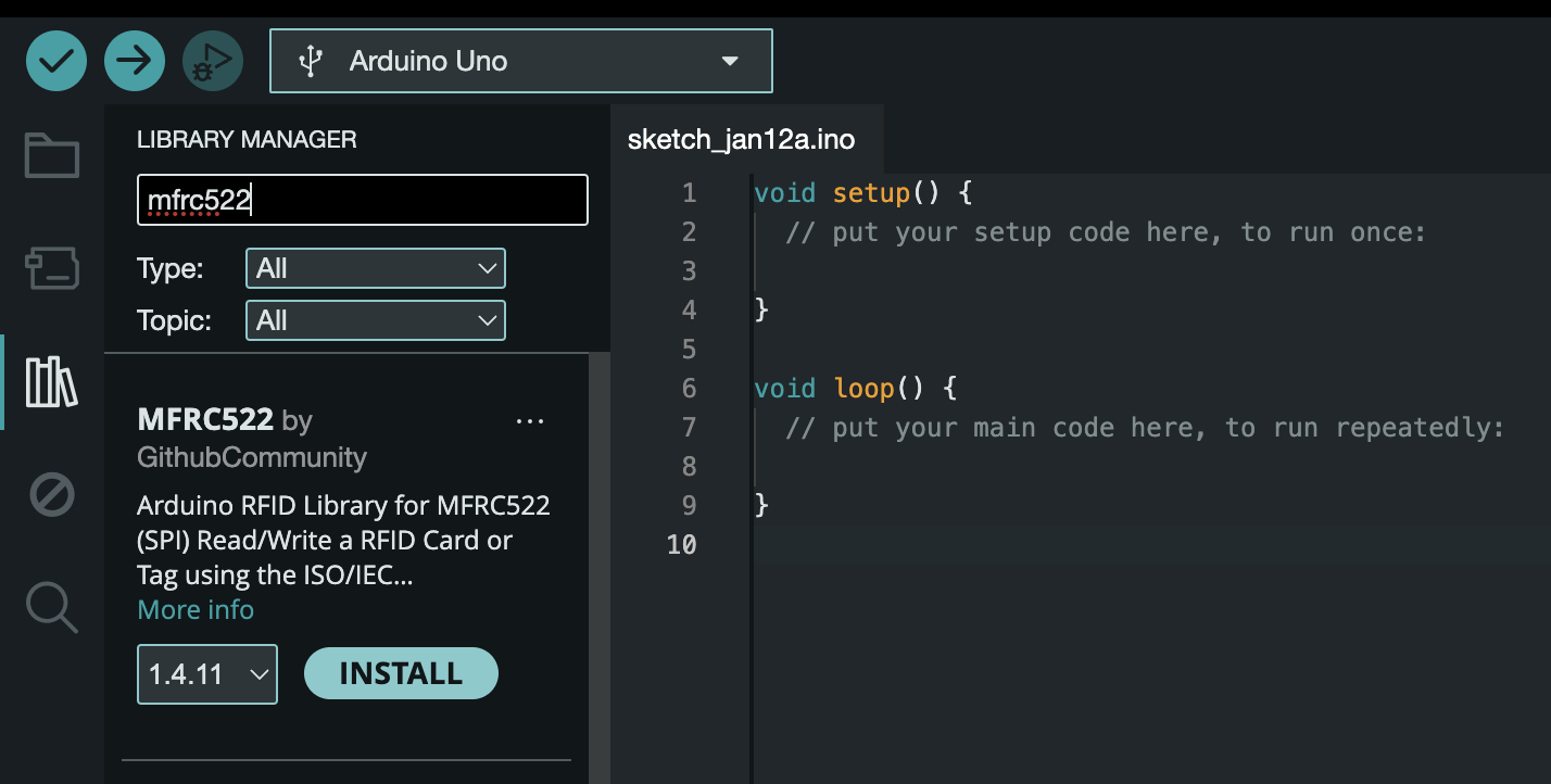
So, finish your wiring. Once you are confident enough in your wiring, it is time to test it using code. We will use a library to help us. A library is code that someone else has written that we borrow functions from. We will install the MFRC522 library. On the left sidebar, there is an icon of books stacked. Click it to open the library manager. Type "mfrc522" and install the library MFRC522 by Github Community.
Now, the library has been installed. Let's open an example. Go to File > Examples > MFRC522 > DumpInfo.
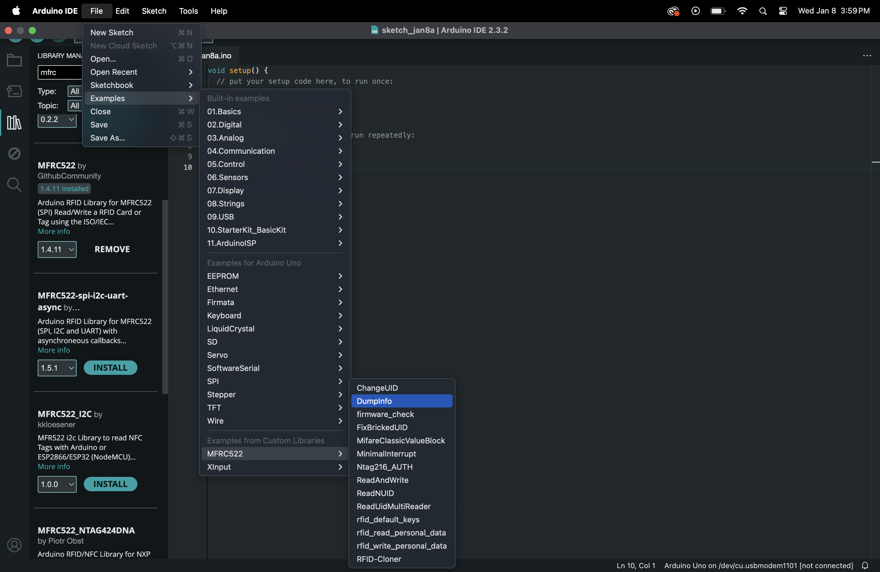
This will open a DumpInfo file. Example files are pre-written files of code that are ready to be ran. There are many examples you can explore at a later time. Now, we will need to make one small change to our DumpInfo file to make it work for us.
Line 41 currently is written as:
#define RST_PIN 9
Change the 9 to a 5 .
This is because we are using pin 5 instead as the reset as we have wired.
Now, try running the file with your Serial Monitor. Tap the RFID tag/card on the reader. You should see info show up! It's a bit messy but at least we can read information. There's a lot of information other than just the UID that we can extract from the card in the Serial Monitor but we just wanted to confirm that it works.
Yay, congrats!🎉Checkoff 3
Show your instructor your wiring and working dump file!Part (4): Making an Access System for your ID (20 mins)
We can extract information from the cards, but we don't do anything with the UID yet. We'll make a simple Access System. A green LED will flash when the correct card is read while a red LED will flash when a wrong card is read. Let's construct our circuit first. We only need to make a small addition. The same way that we did the LED circuit in a previous part, wire one circuit for a green LED and one for a red LED. The green LED should use Pin 2, and the red LED should use Pin 3. The picture is a little wrong.

The schematic above shows the whole circuit you should have. The Green LED is connected to Pin 0 while the Red LED is connected to Pin 1. The RFID circuit itself stays the same.
Once you feel confident that your circuit is correct, it's time to test it with some code. We will go step-by-step with this code and keep appending to the same file. Make a new file in Arduino (File > New Sketch).
#include <SPI.h> //import libraries like this
#include <MFRC522.h>
First, we import our libraries to write less code from scratch ourselves.
#define RST_PIN 9
#define SS_PIN 10

// Create instances
MFRC522 mfrc522(SS_PIN, RST_PIN);
Then, we will define names for certain pins that we will reuse in the code. Instead of using the pin number, we can just use the real english name for easier understanding.
byte readCard[4];
String MasterTag = "873FA939";	// REPLACE this Tag ID with your Tag ID!!!
String tagID = "";
Now, we will make some variables. Variables hold values in names. We also make an MFRC522 instance. This is basically a big custom variable with many properties, in a way.
void setup()
{
    // Initiating
    Serial.begin(9600);
    SPI.begin(); // SPI bus
    mfrc522.PCD_Init(); // MFRC522
    Serial.println("Access System");
    pinMode(1, OUTPUT);
    pinMode(0, OUTPUT);
    digitalWrite(1, LOW);
    digitalWrite(0, LOW);
}
Now, we want to make our setup code. This will run only once and initialize everything we need.
void loop()
{
    // Wait until new tag is available
    // the inside code executes when a valid tag is present
    while (getID())
    {
        Serial.println(tagID);

    if (tagID == MasterTag)
    {
        Serial.println(" Access Granted!");
        digitalWrite(0, HIGH);
        delay(2000);
        digitalWrite(0, LOW);
    }
    else
    {
        Serial.println(" Access Denied!");
        digitalWrite(1, HIGH);
        delay(2000);
        digitalWrite(1, LOW);
    }
    delay(2000);
    }
}
Then, we can write our loop code that runs multiple times. This will be the code always checking the ID and operating the LEDs.
//Read new tag if available
boolean getID()
{
    // Getting ready for Reading PICCs
    if ( ! mfrc522.PICC_IsNewCardPresent()) { //If a new PICC placed to RFID reader continue
        return false;
    }
    if ( ! mfrc522.PICC_ReadCardSerial()) { //Since a PICC placed get Serial and continue
        return false;
    }
    tagID = "";
    for ( uint8_t i = 0; i < 4; i++) { // The MIFARE PICCs that we use have 4 byte UID
        //readCard[i] = mfrc522.uid.uidByte[i];
        tagID.concat(String(mfrc522.uid.uidByte[i], HEX)); // Adds the 4 bytes in a single String variable
    }
    tagID.toUpperCase();
    mfrc522.PICC_HaltA(); // Stop reading
    return true;
}
The getID() function is a custom function. We have to write its logic separately using the MFRC522 library functions.
So your entire file should look something like this:
#include <SPI.h>
#include <MFRC522.h>

#define RST_PIN 9
#define SS_PIN 10

byte readCard[4];
String MasterTag = "873FA939";	// REPLACE this Tag ID with your Tag ID!!!
String tagID = "";

// Create instances
MFRC522 mfrc522(SS_PIN, RST_PIN);

void setup()
{
    // Initiating
    Serial.begin(9600);
    SPI.begin(); // SPI bus
    mfrc522.PCD_Init(); // MFRC522
    Serial.println("Access System");
    pinMode(3, OUTPUT);
    pinMode(2, OUTPUT);
    digitalWrite(3, LOW);
    digitalWrite(2, LOW);
}

void loop()
{
    //Wait until new tag is available
    while (getID())
    {
    Serial.println(tagID);

    if (tagID == MasterTag)
    {

        Serial.println(" Access Granted!");
        digitalWrite(2, HIGH);
        delay(2000);
        digitalWrite(2, LOW);
    }
    else
    {
        Serial.println(" Access Denied!");
        digitalWrite(3, HIGH);
        delay(2000);
        digitalWrite(3, LOW);
    }


    delay(2000);
    }
}

//Read new tag if available
boolean getID()
{
    // Getting ready for Reading PICCs
    if ( ! mfrc522.PICC_IsNewCardPresent()) { //If a new PICC placed to RFID reader continue
        return false;
    }
    if ( ! mfrc522.PICC_ReadCardSerial()) { //Since a PICC placed get Serial and continue
        return false;
    }
    tagID = "";
    for ( uint8_t i = 0; i < 4; i++) { // The MIFARE PICCs that we use have 4 byte UID
        //readCard[i] = mfrc522.uid.uidByte[i];
        tagID.concat(String(mfrc522.uid.uidByte[i], HEX)); // Adds the 4 bytes in a single String variable
    }
    tagID.toUpperCase();
    mfrc522.PICC_HaltA(); // Stop reading
    return true;
}
Yay, we’re finally done with the code!🎉
Now, we're in the homestretch to make it only work with ONLY YOUR student ID.
- Open your Serial Monitor.
- Try running the code:
- If it runs without errors, that’s great 👏.
- If there are 👾 errors 👾, try debugging the code and check the error message.
- Try solving it on your own, but raise your hand if you need help.
Checkoff 4
Show your instructor your Access System flashing red with your ID. - Tap your student ID card. It should flash red because it hasn't been set as the master ID yet.
- The ID number should appear in the Serial Monitor.
- Replace the ID number in the line that sets
MasterTagat the beginning:- For example, if your ID number is "123", change the line to: String MasterTag = "123";
- After making that change, run the code again.
- Your green LED should now flash when your student ID is tapped, and red for any other card.
- Congratulations on your custom RFID Access System!
Checkoff 5
Show your instructor your Access System working with only YOUR ID!Discussion & Reflections
- Give a brief overview of how the code works.
- How did we import packages? How do we change the Master ID value?
- Reflect on the design process
- How can we make our wiring cleaner?
- Further Readings