Total Time: 2.5 hours
Quick Links
Lab 7: Building a Mr. Roboto (Part-1): Motors!
This is the first in a series of two labs that will introduce you to building and programming your own robot. In this series, you will learn the basics of DC motors, motor control, sensor integration and algorithm development. In this first lab, we will learn about DC motors and tackle the assembly and motor control. By the end you will have your robot driving a trajectory you designed.
🦺 Safety and Important Tips
(1 minute read)
The voltages and currents we are using are not capable of being harmful, but there are infinite ways to fry your circuit.
Always follow these tips as you complete this and future labs:
- Unpower your circuit when making any change
- Double check your wiring before plugging in
- When soldering, check for bridges between pads
- Many of the components are cheap/fragile, use them only as instructed
🔨 Fabrication Quest of the Day
- Today, you will assemble and drive a robotic car:
- Assemble a robotic car without sensors
- Give basic driving commands
- Your instructors will provide you with the following:
- Laser cut robotic chassis (x1)
- Motors + mount (x2)
- Ardiuno + motor shield (x1)
- Ardiuno mount (x1)
- Ultrasound + bracket (x1)
- Caster wheel + bracket (x1)
- Fasteners
Ask if you have trouble finding anything.
🏗️ Software & Hardware
Software:
- Ardiuno IDE
Hardware:
Machines:
- Soldering Iron
Part (1): Understanding Code and Testing the Motors (25 mins)
We are using the L293D motor shield. It has support for 4 DC motors (or 2 steppers) and 2 servos. We can also power the motors and Ardiuno through the shield. We are using the AFMotor library because, while we technically don’t need it, libraries make our code easier to write and read. We don’t have to worry about the exact pins and values we are writing to or creating our own PWM signals.
We are going to start this lab by understanding how we can control our motors using the AF_Motor library you installed. Then we will test the motors and make a function that will be even better at controlling the motors.
- Download Motor Library Click the books icon on the left side of the Ardiuno IDE and install "Adafruit Motor Shield library"
- Initialize the library at the very top of the script (above setup). This tells Ardiuno that you can use functions from this external library
- Create motor objects for two motors above setup.
- Set motor speed in setup. setSpeed only takes a range of 0-255 (0 stopped, 255 full speed). It sends a PWM signal to the motor.
- Now set motor direction in setup. The options are FORWARD, BACKWARD, and RELEASE. RELEASE stops the motors.
- Plug the motor shield into the Ardiuno, making sure the pins are all aligned.
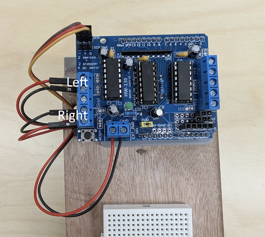
- Get two of the yellow TT motors and plug them into the M1 and M2 terminals on the shield as shown. It actually doesn't matter which terminal has red or black. If you swap it, it will just reverse the direction of the motor
- Upload the code. It should drive your motors forward at a constant speed. It is going to be very slow because we are powering from our laptop's connection to the Ardiuno which cannot supply enough current. This will be fixed once we connect our battery in the next part.
#include <AFMotor.h> AF_DCMotor rightMotor(1); // Motor connected to M1
AF_DCMotor leftMotor(2); // Motor connected to M2void setup() {
rightMotor.setSpeed(255);
leftMotor.setSpeed(255);
} void setup() {
rightMotor.setSpeed(255);
leftMotor.setSpeed(255);
rightMotor.run(FORWARD);
leftMotor.run(FORWARD);
}
Now, alter your code to drive the motors forward for 3 seconds, stop for 1 seconds, drive backward (remember how to change direction) for 3 seconds and repeat (Hint: write code in loop())
Checkoff 1
Ask your instructor for a check-off on completing Part (1). Demonstrate your forward, stop, and backwards script.Part (2) Assembling the Chassis
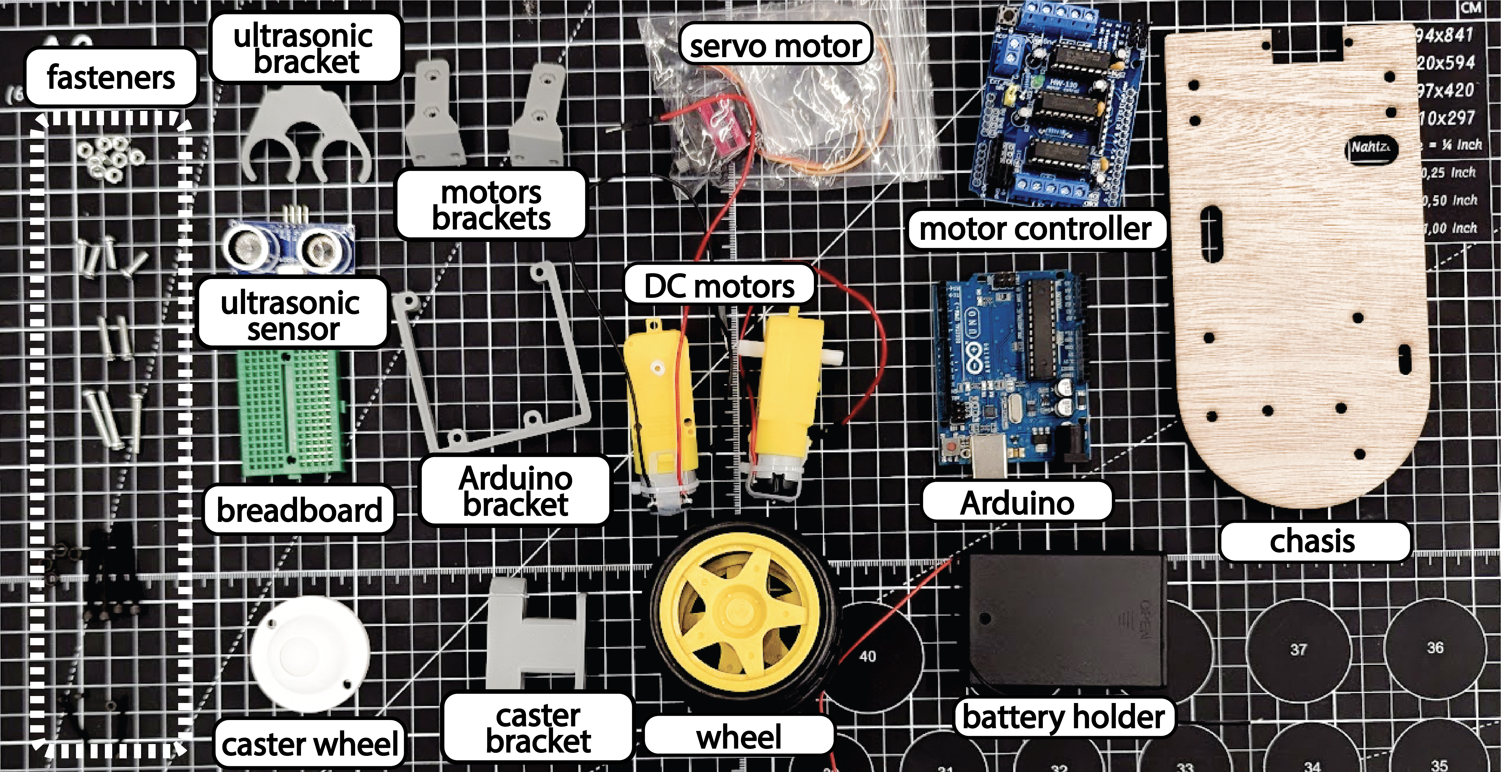
We are now going to assemble our chassis. Make sure you have all the following pieces as shown in the image below.
- Laser cut chassis (x1)
- Motor + mount (x2)
- Ardiuno + motor shield (x1)
- Ardiuno mount (x1)
- Caster wheel + bracket (x2)
- M2x12 (servo)
- M3x10 (motor mount))
- M3x25/M3x30 (motors))
Now attach components to the laser cut chassis in the following order. Don't do it out of order. you can use the gridlines on the cutting matts in between desks to determine fastener length.
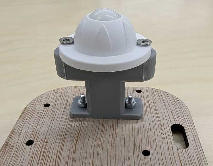
- Attach the ball caster to its mount using the screws (the pointy ones). Then dasten the ball caster mount to the chassis using 3mm x 8mm (x2) bolts.
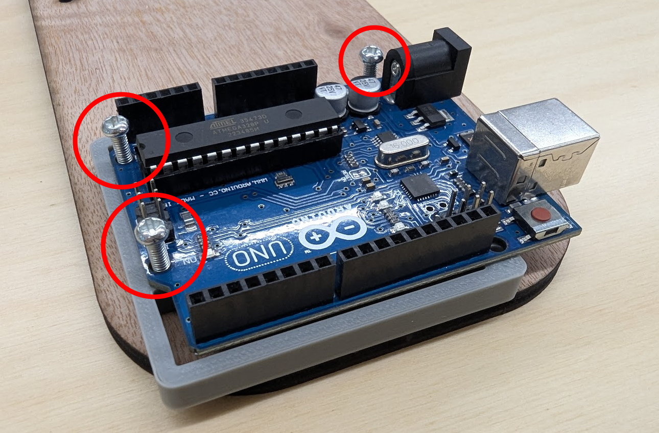
- Attach the Ardiuno (without shield) to its mount and the chassis using 3mm x 16mm (x3) bolts. Then add the shield.
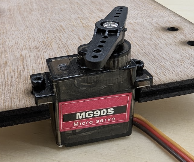
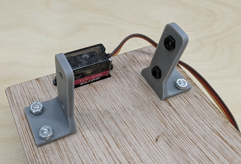
- Use the small screws in your kit to attach the servo to the front of the chassis. The hole is intentionally offset so that the axis of the servo is aligned with the midline of the robot.
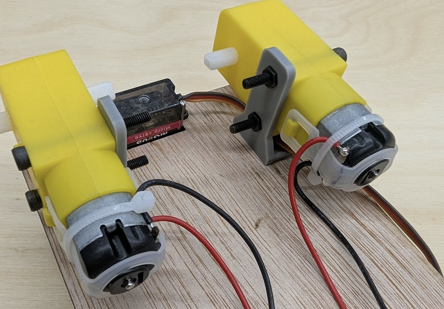
- Attach the motor mounts to the chassis using 3mm x 10mm (x4) bolts. Place a M3 nut in each hexagonal cutout.
- Use 3mm x 25mm (x2) bolts to attach the motors to the motor brackets.
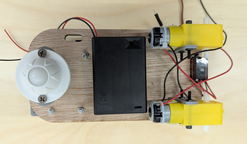
- Attach the battery pack to the bottom of the chassis using double sided tape. The switch should be facing down.
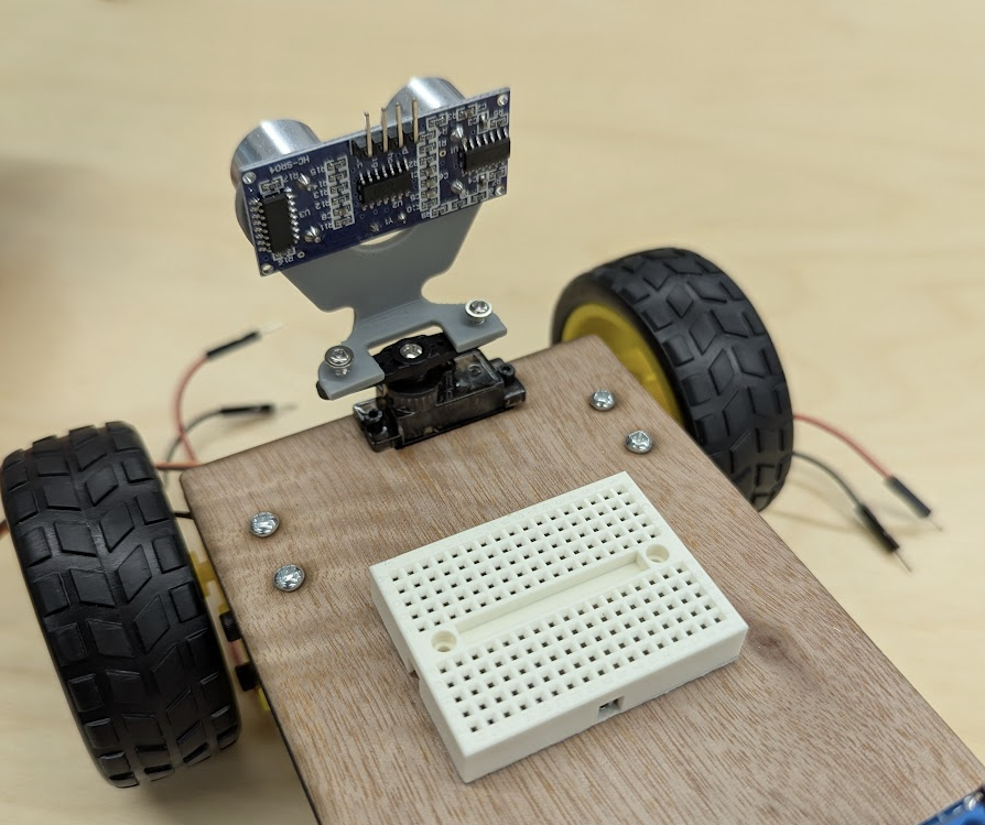
- Stick mini breadboard in the orientation depicted and add the Ultrasound sensor with its bracket to the servo
- Add wheels. Push them on fully, but be careful not to snap the motor mounts.
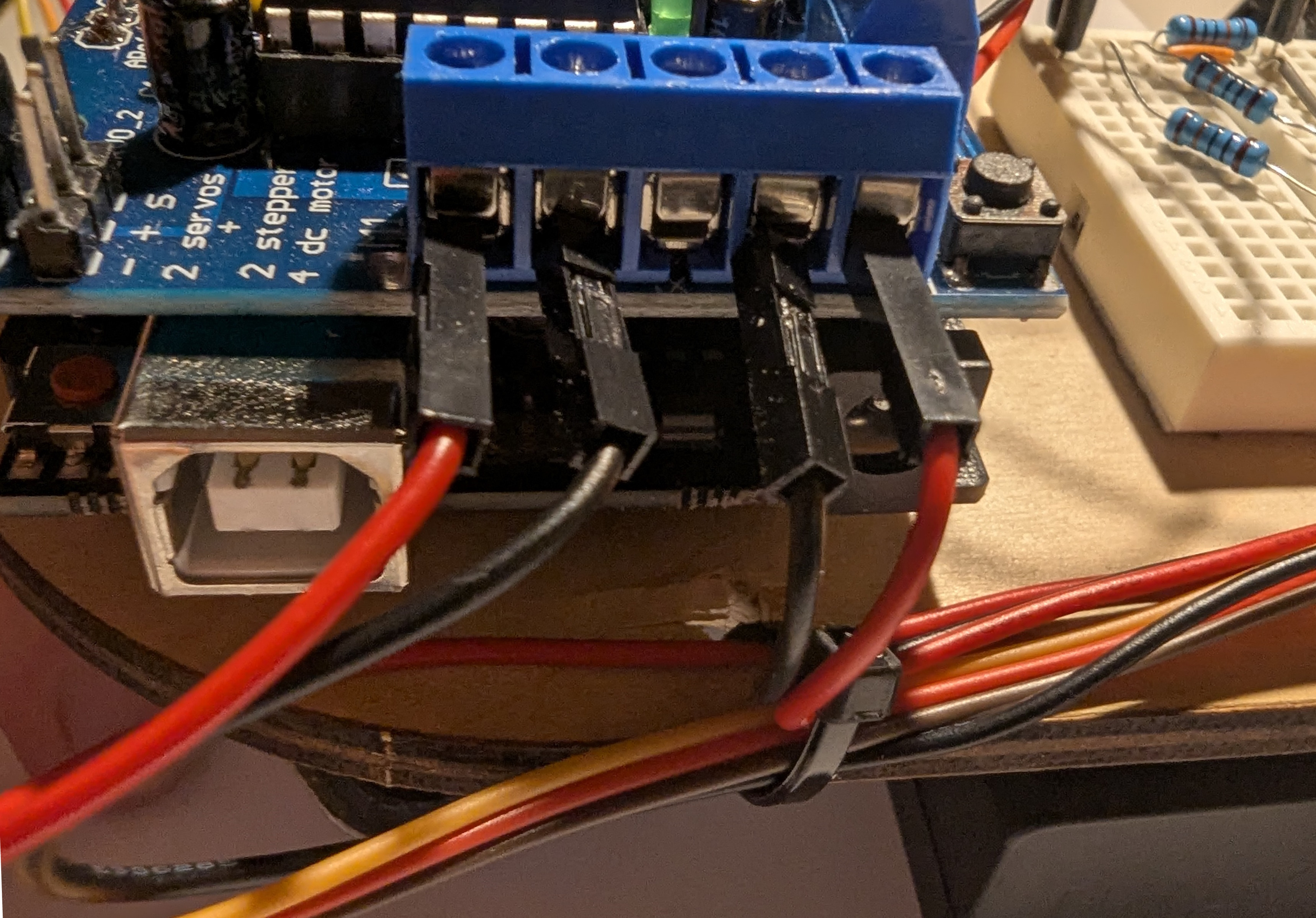
Now we need to plug in the motors and battery bank to the Ardiuno Shield.
- Feed the servo wires through the back hole and connect to the shield as shown. THE YELLOW WIRE IS SIGNAL, BROWN IS GND.
- Feed the motors wires through the back hole into the screw terminals as shown. M1 should be the left motor, and M2 the right motor.
- Finally, attach the power cables to the shield being careful to not swap the power wires.
Congrats! You have built a robot.
Checkoff 2
Ask your instructor for a check-off on completing Part (2). We will provide your batteries upon checkoff completion.Part (3) Driving Straight
We are now going to control our robot
- Using your motor drive code from above, try driving your robot in a straight line by setting both motors to the same speed. Does it drive straight?
- Adjust the relative motor speeds until your robot drives roughly straight.
- Create a `driveStraight(millis)` function to drive straight for a set time. Use `void` as the return type since it doesn't return a value. Fill in the function with the values you found earlier and place it at the end of the script.
- Test it by driving forward for 0.5, 1, 3 seconds
void driveStraight(int millis) {
    // TODO: Fill in the body of this function
}
Part (4) Creating Turning Functions
- Try to command your robot to turn in place exactly 90 degrees counter clockwise. How should each motor be commanded? Set a turn speed, and just alter the duration of turn to dial in 90 degrees.
- Using this timing, fill in the body of the function called turnRight(). Then do the same process to create turnLeft(). They won't necessarily have the same timings. Place both functions at the end of your script.
void turnRight() {
    // TODO: Fill in the body of this function
}
void turnLeft() {
    // TODO: Fill in the body of this functions
}
Part (5) Driving a Loop
In the loop() of your code, use your turning and driving functions to drive in a square with side length 50cm clockwise. Do it again going counterclockwise. How well does it return to its starting location? What might cause this? What potential sensors could we use to fix this?
You may have noticed that it was difficult to get your robot to drive straight and turn a desired amount consistently. This is because the robot is open-loop. It has no idea where it is or where it is going. We are going to close the loop next lab by adding sensors so the robot can detect where it is and where it wants to go.
Part (6) Remix Driving!
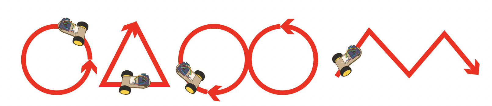
Now that you have a robot that can drive as you command it, try driving in more interesting shapes. Here are some ideas to get you started:
- Drive in a circle with a desired radius
- Drive in an n-sided polygon (square, hexagon, octagon etc). Can you make a function that can take in a number of sides and drives in that shape?
- Drive in an infinity symbol
- Drive in the shape of some mathematical function
This will be the video that shows up on your portfolio, so make it drive well.