Total Time: 1 hour and 45 mins
Quick Links
- Introduction & Safety
- Fabrication Quest
- Software & Hardware for the Lab
- Part (0): Download Processing
- Part (1): Getting a Preliminary GUI
- Part (2): Adding a Button
- Part (3): Adding Serial Communication in Processing
- Part (4): Testing the Game with Keyboard and Breadboard
- Part (5): Learning Soldering
- Part (6): Test the Guitar Hero Game Finally
- Discussion & Reflections
Lab 9: Let's Make a Guitar Hero Game!
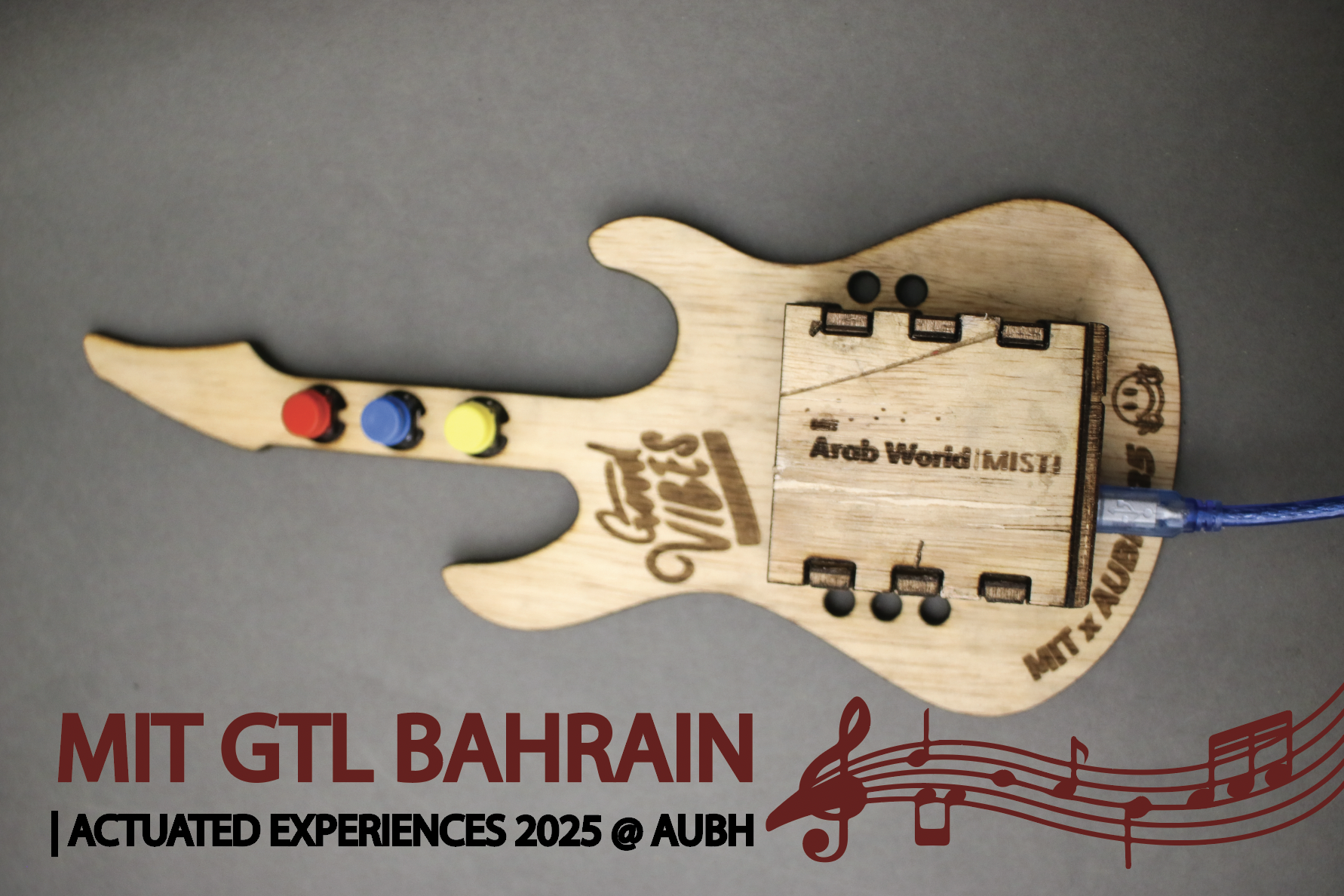
🦺 Introduction & Safety
(1 minute read)In the game Guitar Hero, the user interacts with a screen with colored markers. Whenever the colored markers reach the bottom line, the player must press the associated buttons in time with the music. This screen that the user witnesses is known as a GUI, graphical user interface.
In this lab, you'll create a Guitar Hero game GUI and custom-built guitar while learning how to:
- ✅ Code up a GUI using Processing
- ✅ Learn how to solder electronics
- ✅ Package electrical components together in a clean way
Before we start, please make sure you understand the following safety precautions:
- Soldering Iron Temperature: Ensure that the soldering iron is never left unattended. It reaches temperatures of ~500 degrees Celsius so never make it touch anything it is not supposed to.
- Lead Poisoning: Most solder contains lead. This is very toxic if ingested. Always wash your hands immediately after soldering and never touch your face.
🔨 Fabrication Quest of the Day
- Today, you will code a GUI for Guitar Hero:
- (A) A GUI in Processing using Java (x1)
- And finish the electronics on the lasercut guitar:
- (B) Lasercut Guitar with clean electronics (x1)
- (B) The Guitar base (x1)
- (C) Electrical components (buttons, wire, etc.) (x1)
🏗️ Software & Hardware
Software:
- Processing
- Arduino IDE *Should have downloaded in a previous lab*
PPE:
- Safety glasses
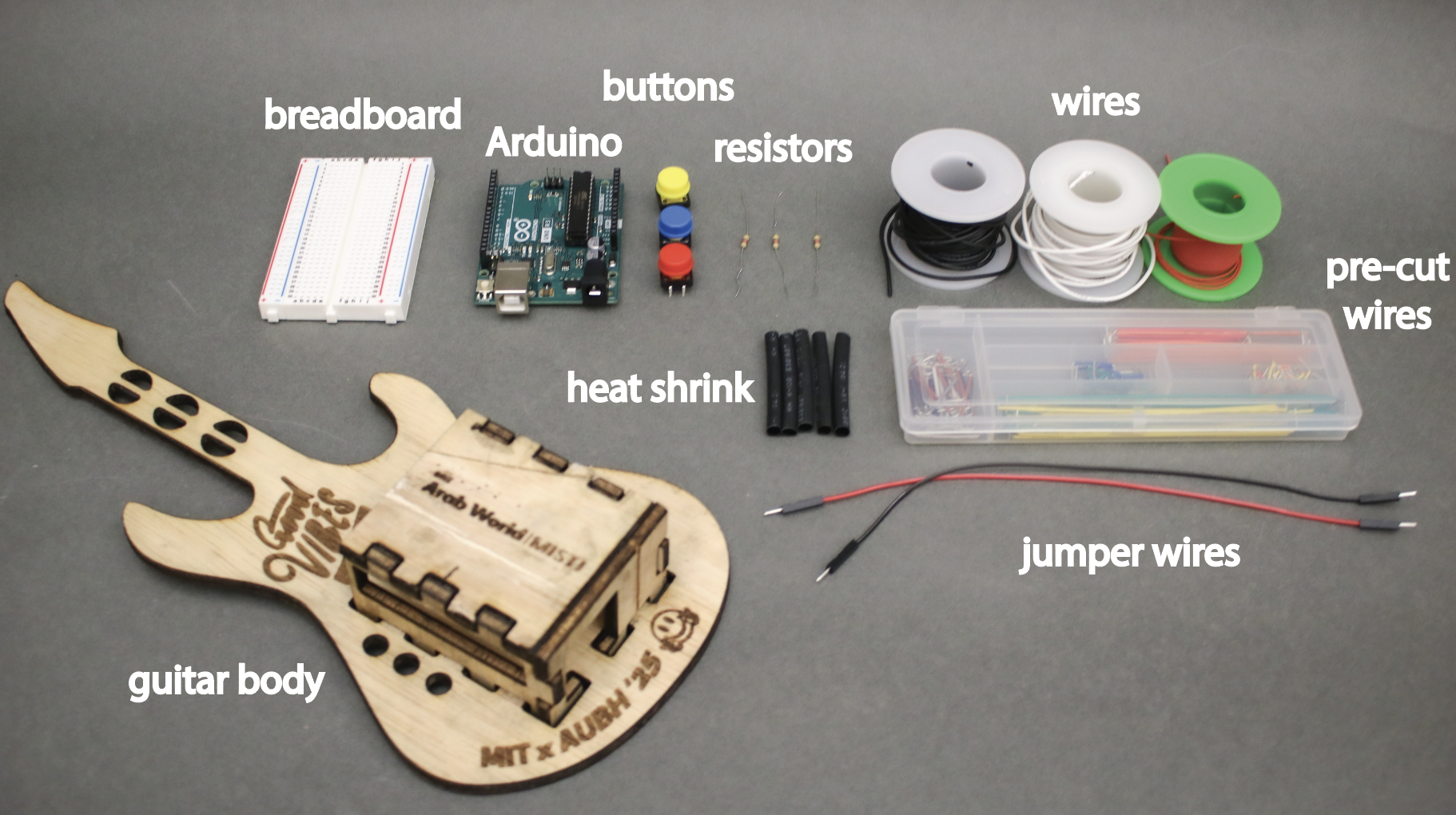
Hardware:
- Pre-lasercut guitar
- Wire
- Wire Cutter
- Buttons (x3)
- Solder
- Zipties
- Electrical Tape
- Arduino Uno
- Multimeter
- Laptop
Machines:
- Soldering Iron
Part (0): Downloading Processing and its libraries
Setup:
- Download Processing (5 mins)
- Install ControlP5 Library for the GUI
- Open Processing
- Click Sketch > Import Library… > Manage Libraries > ControlP5 > Install
- Click Sketch > Import Library… > Manage Libraries > Serial
Part (1): Getting a Preliminary GUI (10 mins)
Processing uses a programming language called Java. Just like Arduino, it has two main functions: setup() and draw(). setup() is similar to the setup() in Arduino. It runs once at the beginning. draw() is synonymous with loop() from Arduino where the function runs over and over. draw(), in fact, runs 60 times a second. This means that you can make simple animations!
To make a basic window, we will introduce you to a library, controlP5. A library is basically someone else's code and you borrow the functions that they have written and simply call them. Most libraries have their documentation online. Learning to look up documentation is an important skill for any programmer. The controlP5 library can be found here.
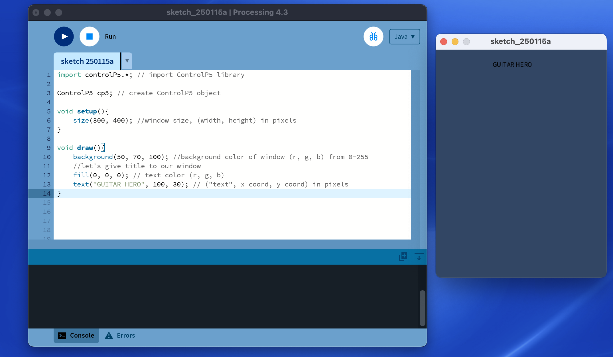
To use the library, you have to import it before you start using it. We won't go deeply into it, but there are objects in programming that contain certain properties. In the following code, we make a ControlP5 object called cp5. This oject has properties and functions like adding buttons. And to run the code, press the play button on the top left. Let’s test some preliminary code, type this, and run:
import controlP5.*; // import ControlP5 library

ControlP5 cp5; // create ControlP5 object

void setup(){
    size(300, 400); //window size, (width, height) in pixels
}

void draw(){
    background(50, 70, 100); //background color of window (r, g, b) from 0-255
    //let's give title to our window
    // we have a pen we draw with and we select its color with the fill function
    fill(0, 0, 0); // text color (r, g, b)
    text("GUITAR HERO", 100, 30); // ("text", x coord, y coord) in pixels
}
You should get a dark blue window with Guitar Hero.
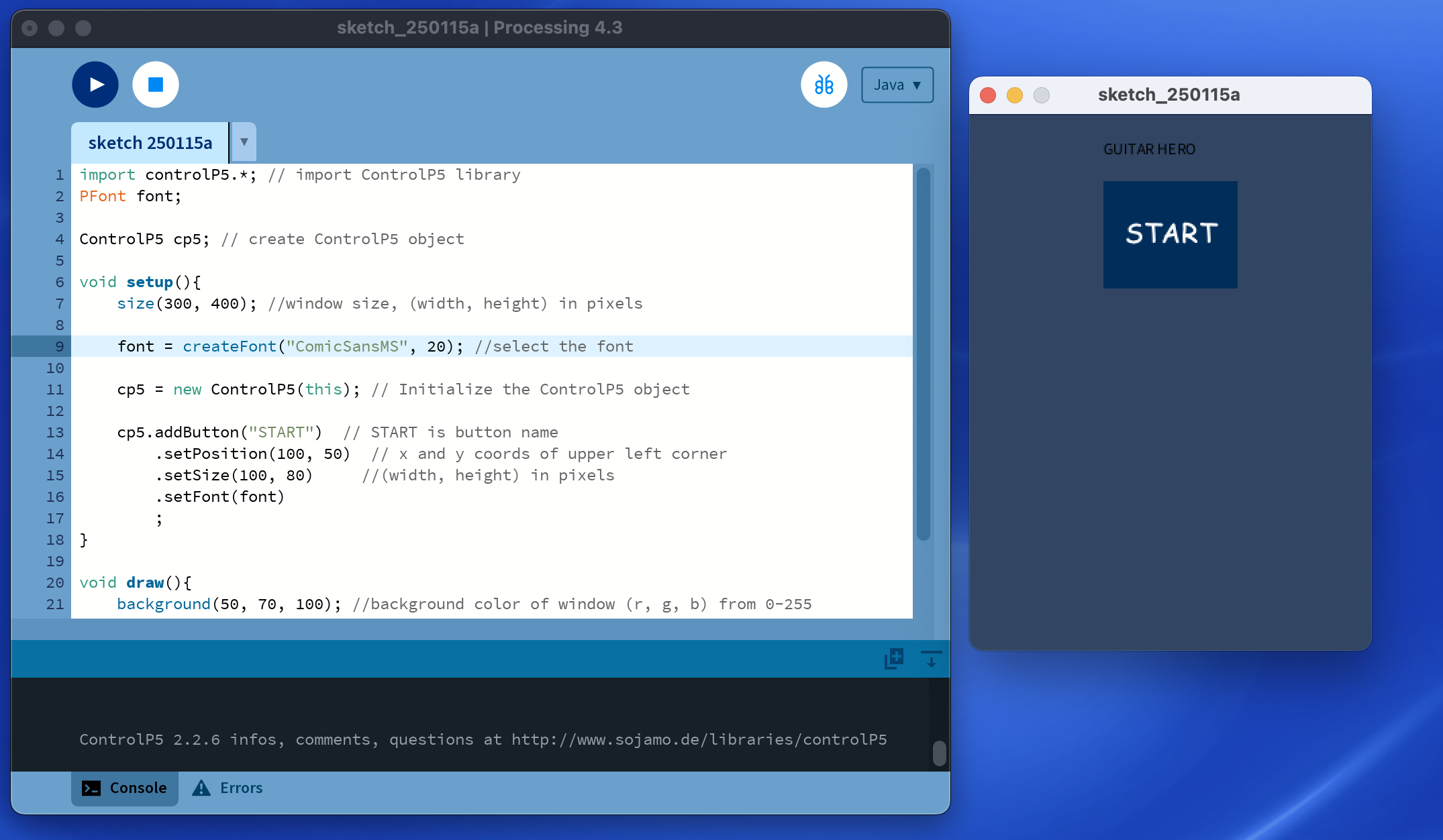
Now, let's add a Button and font. So your code should look like this:
import controlP5.*; // import ControlP5 library
PFont font;

ControlP5 cp5; // create ControlP5 object

void setup(){
    size(300, 400); //window size, (width, height) in pixels

    font = createFont("ComicSansMS", 20); //select the font

    cp5 = new ControlP5(this); // Initialize the ControlP5 object

    cp5.addButton("START")  // START is button name
        .setPosition(100, 50)  // x and y coords of upper left corner
        .setSize(100, 80)     //(width, height) in pixels
        .setFont(font)
        ;
}

void draw(){
    background(50, 70, 100); //background color of window (r, g, b) from 0-255
    //let's give title to our window
    fill(0, 0, 0); // text color (r, g, b)
    text("GUITAR HERO", 100, 30); // ("text", x coord, y coord) in pixels
}
Rerun and you should see a button.
Now since Processing runs the draw function 60 times per second, we can make animations! We'll add some circle code that updates the position every time it runs. Copy paste this code and your IDE should look something like this:
import controlP5.*; // import ControlP5 library
PFont font;

ControlP5 cp5; // create ControlP5 object

// state for circle
float circleY = 0;

void setup(){
    size(300, 400); //window size, (width, height) in pixels

    font = createFont("ComicSansMS", 20); //select the font

    cp5 = new ControlP5(this); // Initialize the ControlP5 object

    cp5.addButton("START")  // START is button name
        .setPosition(100, 50)  // x and y coords of upper left corner
        .setSize(100, 80)     //(width, height) in pixels
        .setFont(font)
        ;
}

void draw(){
    background(50, 70, 100); //background color of window (r, g, b) from 0-255

    //Circle code animation
    // draw current frame based on state
    ellipse(100, circleY, 50, 50);

    // modify state
    circleY = circleY + 1;

    // reset state
    if(circleY > height) {
      circleY = 0;
    }

    //let's give title to our window
    fill(0, 0, 0); // text color (r, g, b)
    text("GUITAR HERO", 100, 30); // ("text", x coord, y coord) in pixels
}
You should get something like this:
Awesome, now you know how to make a basic window, a button, and an animation!
Checkoff 1
Ask your instructor for a check-off on completing Part (1) and showing your animation.Part (2): Adding a Button (15 mins)
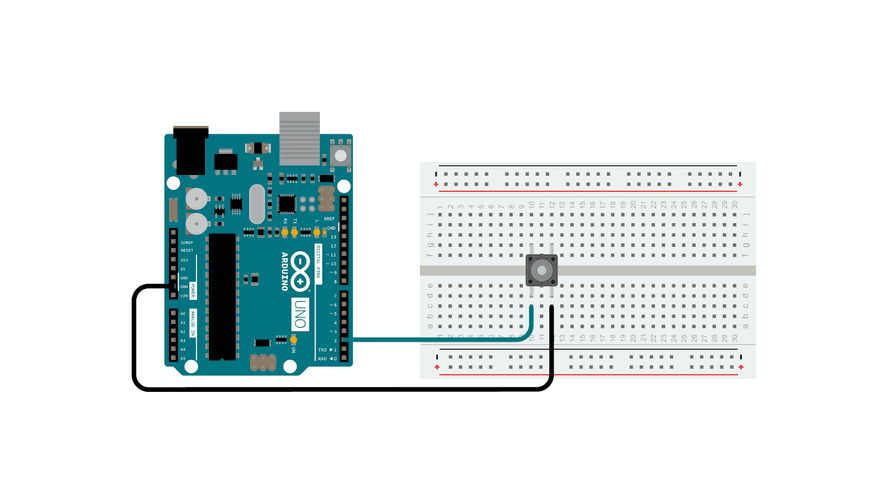
We want our guitar to have buttons. Buttons can read as 3.3 V or 0 V. To understand how the button is wired internally, we have to use multimeter, specifically its continuity mode that we learned about in a previous lab. When the multimeter beeps, you know the two legs of the button are connected. Traditionally, we think of a button with two legs: unconnected when unpressed and connected when pressed. However, the buttons we gave has four legs.
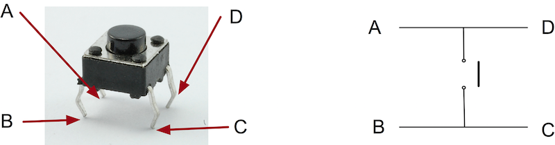
To understand the orientation you need to place the button in, please use a multimeter. Then, you can place a single button on a breadboard like this for example:
Now, open Arduino. Make a new program with the following code in Arduino. There are some lines in the code that are marked with TODO. Please go through these lines and finish those lines of code.
/*
DigitalReadSerial
*/

// digital pin 2 has a pushbutton attached to it. Give it a name:
int pushButtonA = 2;
// digital pin 3 has a pushbutton attached to it. Give it a name:
int pushButtonB = ; //TODO: Put the correct pin number (3)
// digital pin 4 has a pushbutton attached to it. Give it a name:
int pushButtonC = ; //TODO: Put the correct pin number (4)

// the setup routine runs once when you press reset:
void setup() {
// initialize serial communication at 9600 bits per second:
Serial.begin(9600);
// make the pushbutton's pin an input and with a pullup resistor:
pinMode(pushButtonA, INPUT_PULLUP);

// TODO: make the pushbutton's pin an input and with a pullup resistor for pushButtonB and pushButtonC
// HINT: you can basically copy paste the code above for each button
}

// the loop routine runs over and over again forever:
void loop() {
// read the input pin:
int buttonStateA = digitalRead(pushButtonA);
// print out the state of the button:
if (!buttonStateA) {
    Serial.println("A");
}

//TODO: Please do the same thing we did with buttonStateA and Pin 2 for Pin 3 and Pin 4 to print B and C respectively.
//HINT: To make "B" and "C" print, it is mostly copy paste and changing the name

delay(1);  // delay in between reads for stability
}
If you connected the button to Pin 2, then when you press the button, you should see an "A" print in the Serial Monitor. Now, connect two more buttons to Pin 3 and Pin 4 to see a "B" and "C" print.
Checkoff 2
Show that your Serial Monitor prints A, B, C when you press the buttons. Your instructor will also check you understand how to use a multimeter to check the internal wiring of the button.Part (3): Adding Serial Communication in Processing (20 minutes)
Now, let’s try learning how to add Serial communication.
Note: You must close your Serial Monitor in Arduino before running the Processing file, or else you will get the error that the port is busy.
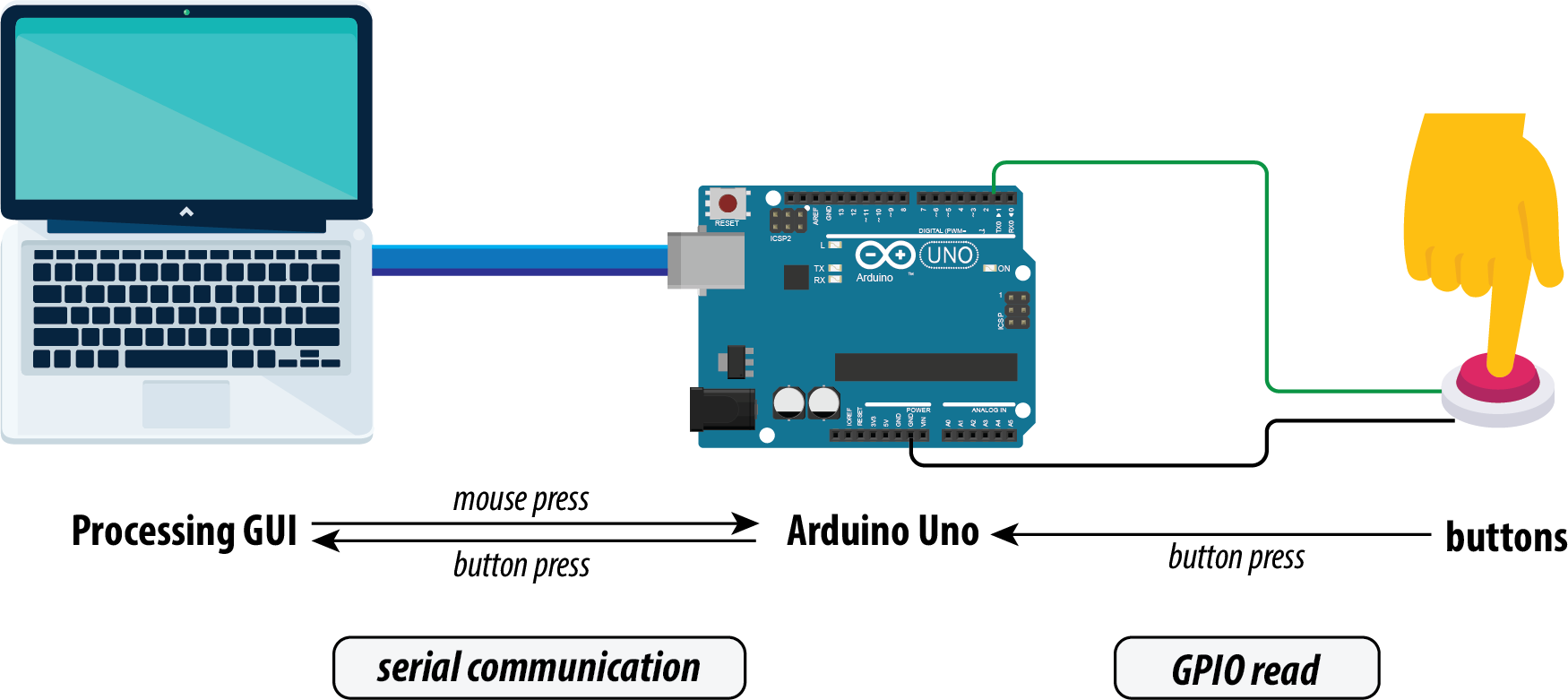
Here is how the Serial works basically:
Replace your program with this code below in Processing in a new file. Look particularly and lines 8 and 9. If the buttons do not print to the Processing terminal, then we are likely using the wrong port. Change the port number to work with your computer. Feel free to ask for help if you have tried multiple port numbers and they have not worked.
import processing.serial.*;

Serial myPort;  // Create object from Serial class
String val;     // Data received from the serial port

void setup(){
    size(300, 400); //window size, (width, height)
    println(Serial.list()); //print all the ports you have and choose the one that is the Arduino
    String portName = Serial.list()[2]; //change the 2 to a 0 or 1 or 3 etc. to match your port
    myPort = new Serial(this, portName, 9600);
}

void draw(){
    background(50, 70, 100); //background color of window (r, g, b) from 0-255
    //let's give title to our window
    fill(0, 0, 0); // text color (r, g, b)
    text("GUITAR HERO", 100, 30); // ("text", x coord, y coord)
    if ( myPort.available() > 0)
    {  // If data is available,
    val = myPort.readStringUntil('\n');         // read it and store it in val
    }
    println(val); //print it out in the console
}
This is communication from Arduino to computer. You can also do communication from Processing to Arduino!
It would be the same process of opening the port and doing myPort.write("something").
Checkoff 3
Show your instructor that you have working Serial communication with Arduino and Processing.Part (4): Testing the Game with Keyboard and Breadboard (20 mins)
Go to this url and download the folder. Guitar Hero Link. To download the zip folder, click the green code button, and finally click download zip. Open the Processing file named rhythmgame.pde. It is under Processing/rhythmgame folder.
Since our game has sound, we need to install the Sound library. Download the Sound library with The Processing Foundation as the author. You do this the same way we did for the Serial and ControlP5 library.
Reminder: You must make sure the Arduino Serial Monitor is closed before running the Processing file.
Navigate to line 68 in the code. Change the location of the trackdata file with the location on your laptop.
// TODO: Load track metadata EDIT THIS LINE BELOW WITH YOUR PC LOCATION
trackData = new TrackData("/Users/STEAM/mit-gtl-bahrain-2025-guitar-hero/Processing/rhythmgame/data/trackinfo.txt");
Now, try running the game with just the arrow keys (left, down, right). If that works, then we can test the Serial. Make sure your Arduino is plugged in and make sure your Serial monitor is closed. This will ensure that information is being written into the port that we can grab from Processing. Now, run the Processing code once more. Your breadboard controller should work now! Don't hesitate to ask questions if you have any. Take a bit of time to understand the Processing code. You will be asked some questions during checkoff of the lab, particularly, about the Serial communication portion. The most notable lines are lines 50-54 and 276-284.
Checkoff 4
Show your instructor that your breadboard controller works. Explain how the Serial code works.Part (5): Learning Soldering (15 mins)
Soldering is a technique to connect two electrical components together. Solder is usually a leaded metal that you melt down and acts as glue. The soldering iron heats up the solder to turn it into a liquid that can flow. For our first step, let's turn on the iron to 450 degrees Celsius. For this whole process, don't be afraid to ask for help from one of your instructors. Soldering can be daunting at first.
This YouTube video shows how to solder on a circuit board and how to solder on wires. The wires part is most relevant to this lab.
Below is also a quick tutorial as well if you are already familiar with soldering:
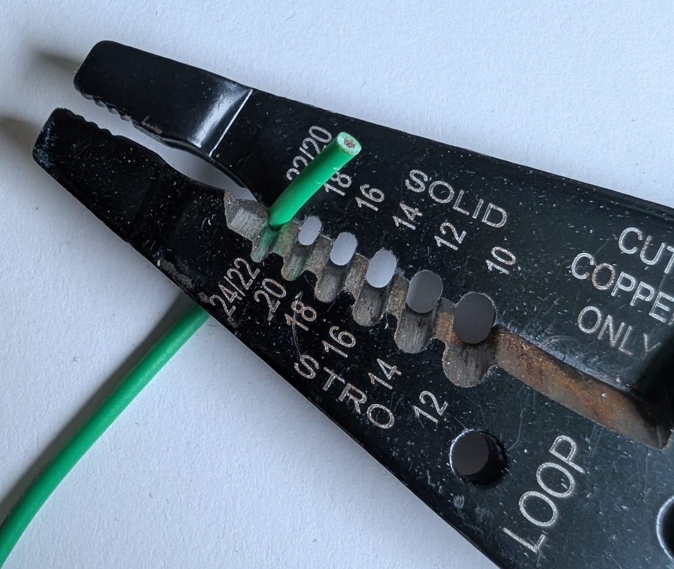
Cut some wire. Strip the wire to expose some of the metal.
Now, bring the solder, soldering iron, the wire, and the leg of the button together. You will see the solder melt and become a glue. It only becomes a glue that keeps components together when it cools and becomes solid. So when it is cooling, make sure that everything is stable and holds together. Using clips to hold things together helps with all of this. This is pictured below.

There's also another technique for putting electrical components together cleanly. So, we used soldering to connect wires together. However, they're just hanging out and can accidentally touch other exposed wires which would make connections that we don't want and, in the worst case, can cause a fire. So, we can insulate the wire by wrapping it in electrical tape or heatshrink. Heatshrink is a plastic tubing that shrinks when heat is applied. We use a heatgun (which spews hot air) to wrap it around the exposed wire. In the gif below, I put the heatshrink over the exposed wire.
After looking at this quick tutorial, go to the solder station and have an instructor help you solder and heatshrink.
Checkoff 5
Your guitar should be soldered and heatshrinked fully now!Part (6): Test the Guitar Hero Game Finally (10 mins)
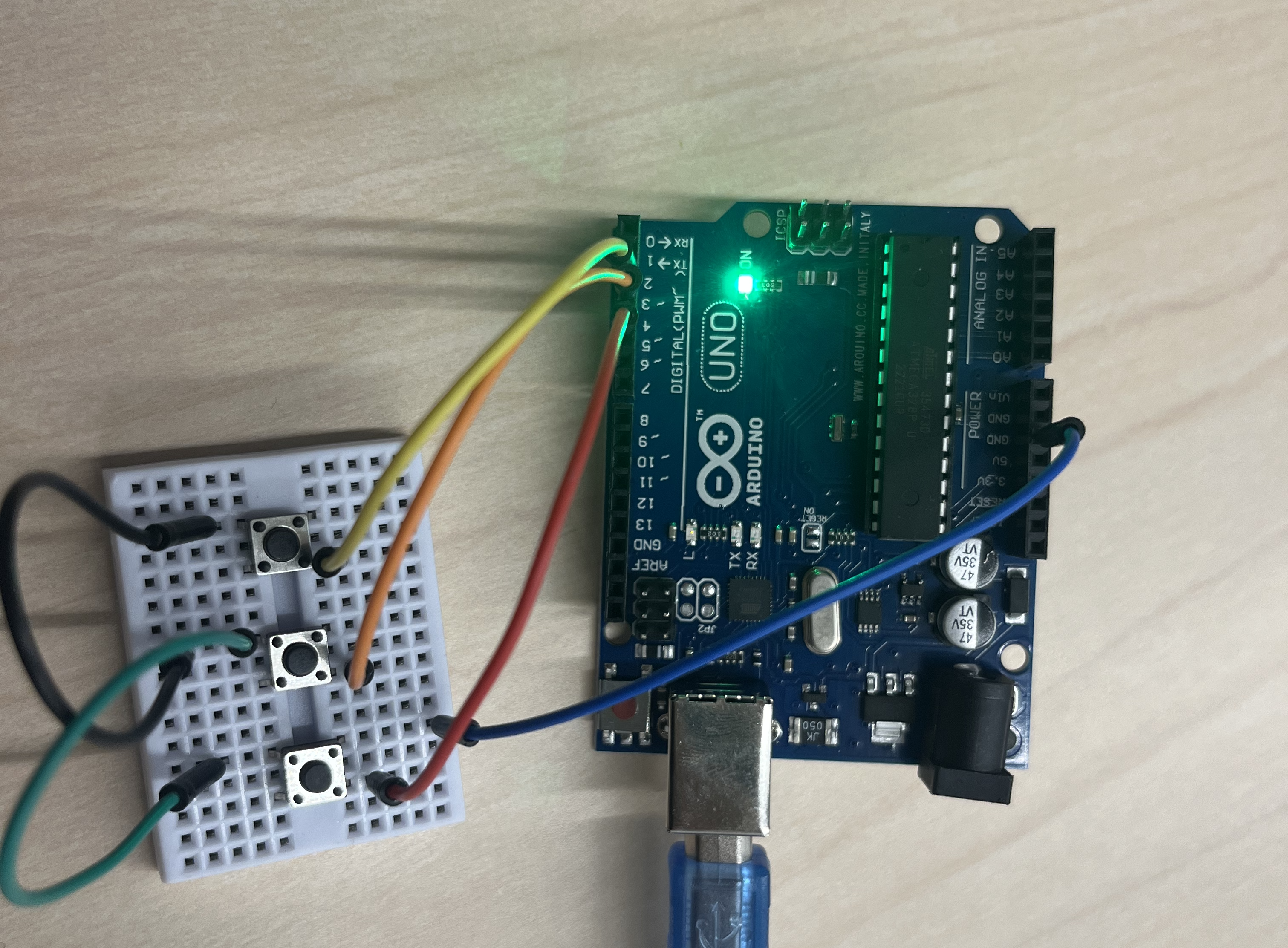
The button closest to the Arduino is for Pin 2, the middle button is for Pin 3, and the farthest button from the Arduino is Pin 4. And the big black wire goes to GND. You can use the same Arduino code that you used for the breadboard (the one that printed A, B, C)! Also, if you come across any issues, make sure your port in the Processing code is correct.
Now, test playing the game on your guitar! Hopefully, the buttons should work and you can see your score increase!
Congratulations, your custom Guitar Hero game and controller are ready! 🎉
Checkoff 6
Show that your guitar works with the Guitar Hero game!Discussion & Reflections
- Give a brief overview of how the code works.
- How are the serial inputs being processed into game inputs?
- How are buttons hits being scored?
- How is the trackdata file used?
- Further Readings