Total Time: 2.5 hours
Quick Links
- Introduction & Safety
- Fabrication Quest
- Software & Hardware for the Lab
- Part (0): Fusion360 Refresher
- Part (1): Sketching Objects and Dimensioning
- Part (2): Filletting
- Part (3): Linear Patterning
- Part (4): Sketching the Triangular Legs
- Part (5): Loading the Finger-joint plug-in
- Part (6): Extruding the Parts
- Part (7): Creating the finger joints
- Part (8): Projecting Sketch Entities
- Part (9): Importing DXF File
- Part (10): Remixing
- Part (11): Exporting DXF File
- Part (12): Lasercutting
- Part (13): Assemble the Calendar and Sand the Edges
- Discussion & Reflections
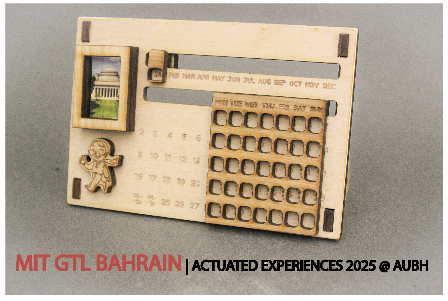
Lab 1: Let’s Laser-Cut a Calendar!
🦺 Introduction & Safety
(1 minute read)Laser cutting is a digital fabrication method that uses a laser to cut or “subtract” materials.
In this lab, you'll create a dynamic laser-cut calendar while learning how to:- ✅ Use Fusion360 for 2D CAD sketches
- ✅ Learn how to make a lasercut sliding mechanism
- ✅ Learn how to CAD finger joints and living hinges
- ✅ Safely operate a laser cutter
- ✅ Post-process and assemble cut parts
Before we start, please make sure you understand the following safety precautions:
- Material Compatibility: Ensure that the material is laser-cuttable, has a thickness under 0.25" (6.35mm), and is cut with the correct power/speed settings.
- Fumes: Keep ventilation on and wait before opening the lid after cutting.
- Eye Protection: Monitor the process without staring directly at the laser.
- Emergencies: In case of fire, do not open the laser cutter lid, simply stop the machine and alert the shop manager immediately.
- Consultation: Always consult the D-Lab shop manager before cutting!
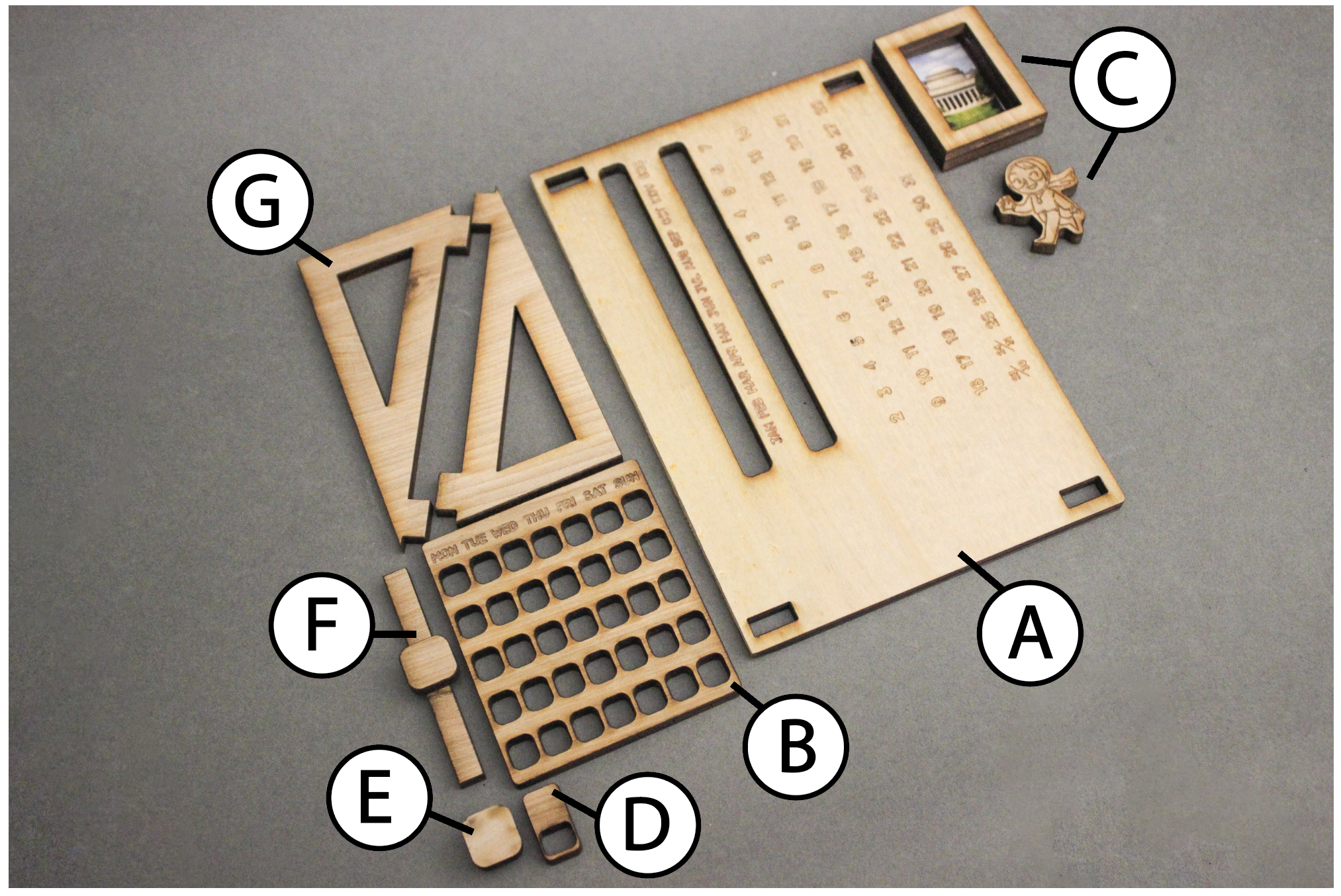
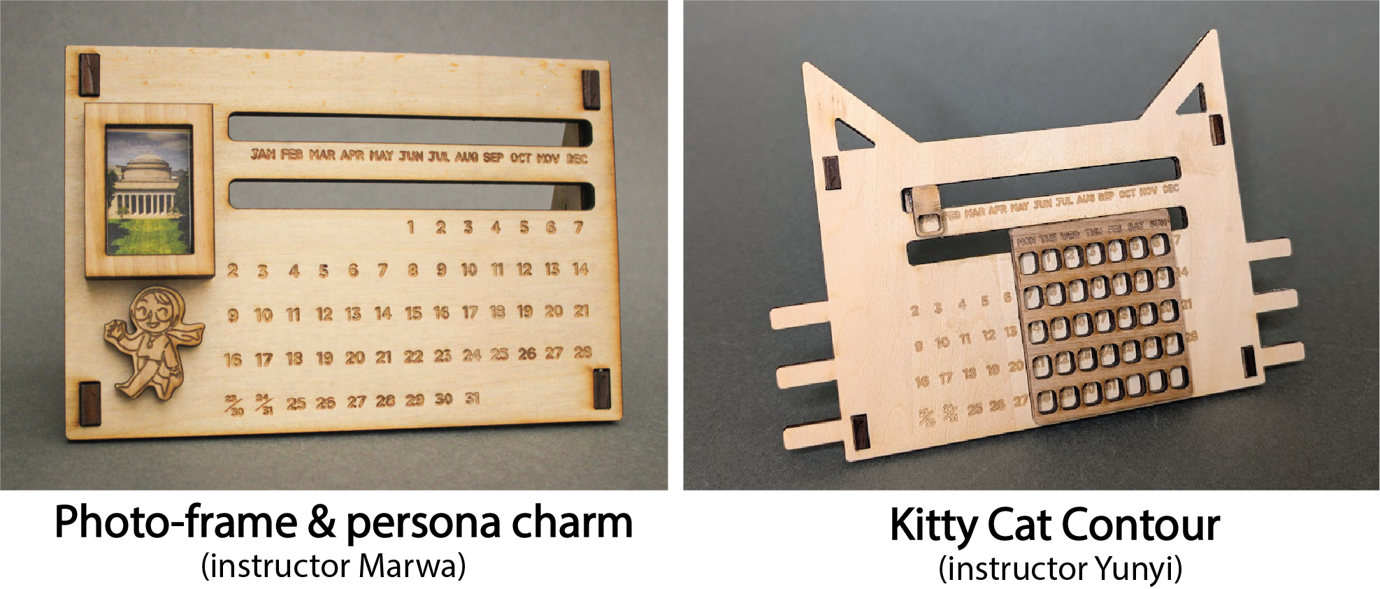
🔨 Fabrication Quest of the Day
- Today, you will CAD 3 parts:
- (A) The rectangular calendar body (x1)
- (B) The day of the month slider (x1)
- (G) The triangular leg joints (x2)
- And fabricate 2+ parts:
- (A) The rectangular calendar body (x1)
- (C) Your own “Remix” to the assignment
Remixing refers to you adding your own touch to a template so that it has your own creative touch to it. This will be a common theme throughout the labs.
Your instructors will provide you with the following:- (B) The day of the month slider (x1)
- (D) Day of the week slider (x1)
- (E) & (F) Slider stoppers (x2)
- (G) The triangular leg joints (x2)
🏗️ Software & Hardware
Software:
- Fusion360 (must download before workshop)
- Adobe Illustrator *Can download through Creative Cloud*
PPE:
- Safety goggles
- Face mask
- Nitrile gloves
Hardware:
Machines:
- Laser cutter
Part (0): Fusion360 Refresher
If you feel a bit rusty on using Fusion360, please refer to the Beginner Lab to get a refresher on basic CADing principles.
Please make sure that your Design History Timeline is toggled ON before you start CADding
Part (1): Sketching Objects and Dimensioning (20 mins)
[Parts 1-4 ONLY Covered in video]
- Create a New Design:
- Open Fusion360 and create a new design by going to File → New Design → Save. Name it "myDynamicCalendar".
- Choose a Plane for the Sketch:
- To begin sketching, we need to pick a plane or surface. In this case, we’ll use a plane.
- Orient yourself to the top view and click on the xy plane. Make sure the "origin" folder is toggled on so you can see the plane.
- Click the Sketch tool icon in the top panel. You’re now in sketch mode.
- Create the Main Rectangle:
- Select the Rectangle tool and click on the workspace to begin drawing. Place the first corner at the origin (the white dot).
- Drag the rectangle outward and click again to place the other corner. This point can be anywhere for now.
- Hit escape or done to stop drawing more rectangles.
- Dimension the Rectangle:
- Select the Dimension tool under Create → Sketch Dimension, or use the shortcut "D".
- Click on the width of the rectangle, drag downward, and click on the workspace. Assign it a value of 115 mm (ie, 11.5 cm).
- Repeat the process for the length, assigning it 170 mm (ie, 17 cm).
- Draw the Slider Holes:
[Part 5 ONLY Covered in video]
- Using the same steps as above, draw another rectangle inside the first one. This will be the hole for the slider.
- Dimension the new rectangle to 120 mm (length) and 8 mm (width).
- Now, dimension the vertical distance from the new rectangle to the main rectangle's top length to 20 mm.
- Dimension again the horizontal distance from the width of the slider hole to the width of the main rectangle to be 8mm (right-side).
- Repeat these steps, ensuring the vertical and horizontal distances are (vertical: 67 mm from bottom), (horizontal: 8mm from right) respectively.
Part (2): Filletting (5 minutes)
Note that the video shows 4 extra rectangles at the corner, but please ignore them-- these were required to be CADed by the Beginner section, but in your case, we will use a plug-in to make them.Filleting is the process of rounding off sharp edges on your design. For laser cutting, filleting is important because sharp corners can create stress points in the material, which may lead to cracks or breakage. Filleting smooths out those corners, improving durability and aesthetics.
Now your design is filleted and ready for a cleaner, more durable laser cut!
Checkoff 1
Show the filetted corners to your instructorPart (3): Linear Patterning (10 minutes)
Next, let's design the small day-of-the-month slider:
- Draw the Outer Rectangle:
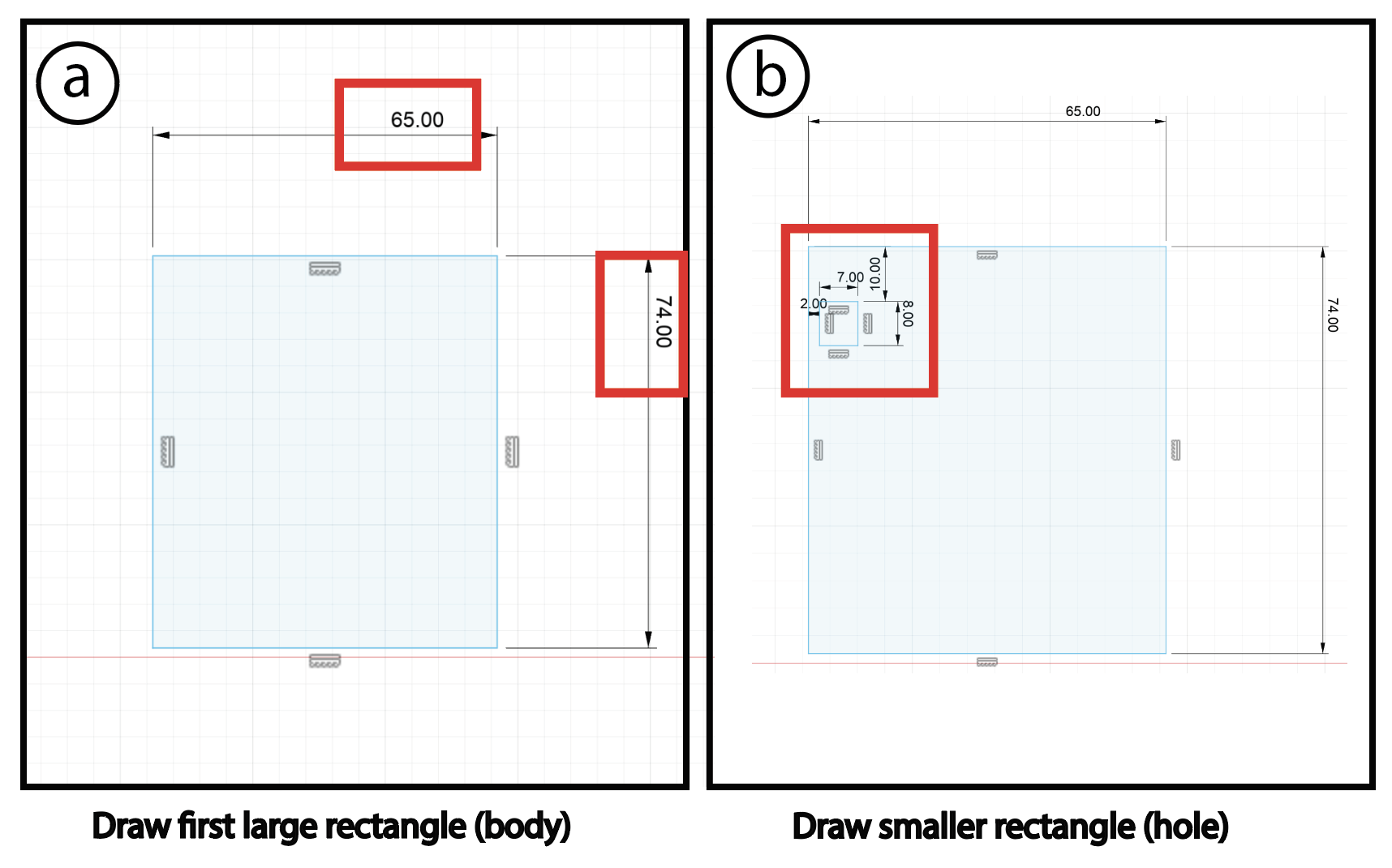
- Similar to Part(1), draw a rectangle. Dimension it to 74mm by 65mm, and make sure it’s not overlapping the previous design's main.
- Create a Smaller Rectangle Inside:
- Inside this rectangle, draw a smaller one representing the holes for days of the month. Dimension it to 7mm by 8mm.
- Place this smaller rectangle 10 mm from the top and 2 mm from the side (left).
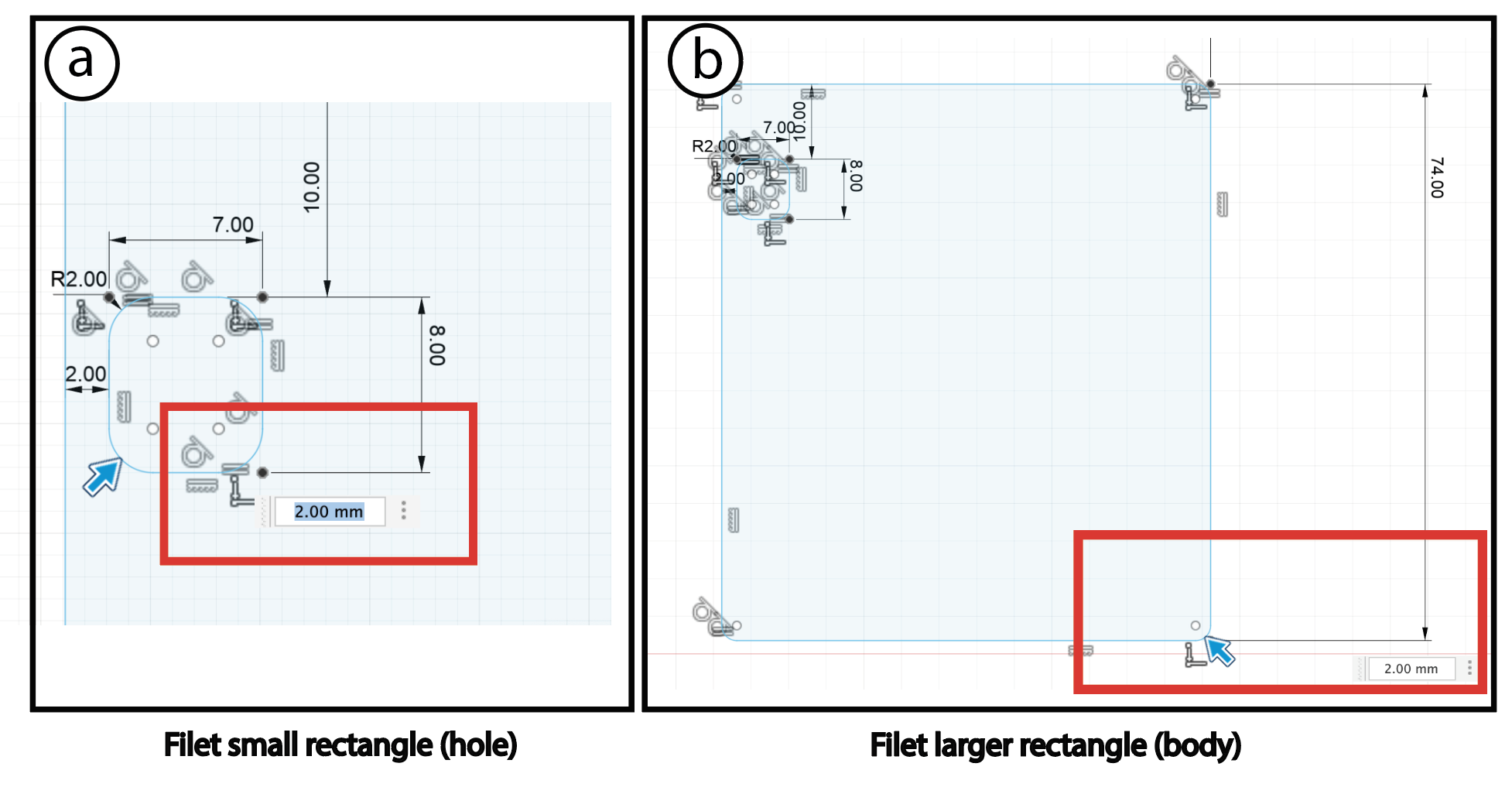
- Fillet the Rectangles:
- Input the fillet radius as 2 mm.
Now that we have filleted our rectangles, let’s create the remaining rectangles.
- Adding Multiple Rectangles:
- Instead of creating X more rectangles manually, let’s use linear patterning.
- What is Linear Patterning?
- Linear patterning replicates an object along a straight line, horizontally, vertically, or both. It’s a shortcut to avoid repetitive work.
- Use the Linear Pattern Tool:
- Select the part you just made.
- For the horizontal patterning, set spacing to 9 mm and the number of copies to 7.
- For the vertical patterning, set spacing to 13 mm and the number to 5.
- Reflect:
- Why don’t we use mirroring here?
Checkoff 2
Show your linear patterned result, and answer the reflection questionPart (4): Sketching the Triangular Legs
Video Summary
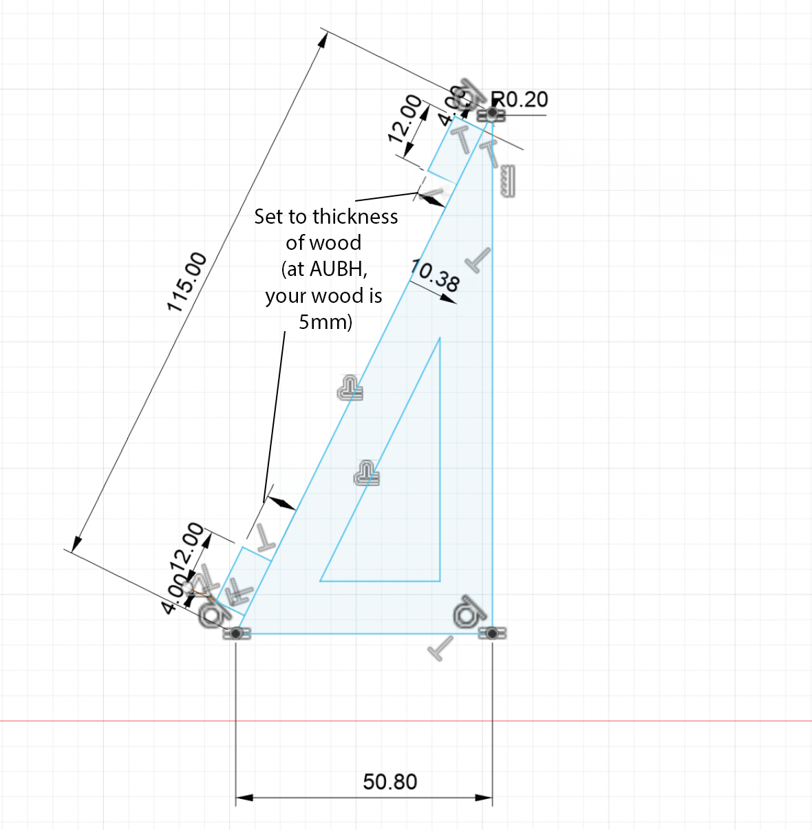
- Draw the triangle: Draw a right triangle with a base of 50.8mm, and a hypotenuse of 115mm on the YZ axis.
- Offset the triangle: Offset the triangle by 10.4mm to create a smaller triangle (this hollows out the big triangle).
- Draw finger joints: Draw two rectnagles of dimensions 12mm x thickness of wood you are using which is 5mm (at MIT, we were using 0.25" thick wood, which is 6.32mm) and make them along the hypotenuse. Let each of these rectangles be 4mm away from the edge.
- Fillet: Fillet the sharp edges (except for the finger joints) by a radius of 0.2mm
To create finger joints seamlessly and quickly (to help you with your final project or remix), we will use a plug-in, which also introduces you to plug-in loading and requires extruding the part.
Part (5): Loading the Finger-joint plug-in
Note Please SAVE your file before you attempt this part. You might need to close Fusion and restart it before seeing the Plug-in appear for you.Video Summary:
- Download the Plug-in: Go to the following link to donwload the Finger Joint plug-in. Click on the green button that says "Code", and choose under https "download zip file"
- Unzip the File: Unzip the file in your downloads folder.
- Rename the unzipped folder: Remove the "-master" at the end of the folder's name.
- Move the folder to the Fusion360 Add-ins folder:
- Mac users: Open Finder, click "Go" in the menu bar, select "Go to Folder" (or press Shift + Command + G), paste
/Users/NameofYourUserGoesHere/Library/Application Support/Autodesk/Autodesk Fusion 360/API/AddIns(replacing NameofYourUserGoesHere with your username), and click "Go". - Windows Users: Follow similiar steps compatible with windows to access the "Add-ins" file. (eg.
* Windows: `%AppData%\Autodesk\Autodesk Fusion 360\API\AddIns`)
- Mac users: Open Finder, click "Go" in the menu bar, select "Go to Folder" (or press Shift + Command + G), paste
- Find the Plug-in in Fusion: Find the plug-in under the "Modify" tab in Fusion360.
Part (6): Extruding the Parts
Using the finger-joint plug-in requires us to have the parts be extruded 3D models. This is why we need to extrude our 2D geometry.Video Summary:
- Draw Aligenment Construction Line : Create two vertical construction lines that are 4mm away from the edge of the calendar body.
- Extrude the triangle : Extrude the triangle to the thickness of the wood piece provided to you which is 5mm. In the video and at MIT, we were using 0.25" wood stock.
- Extrude the calendar body: Following the same steps above, extrude the calendar body.
- Align the hypotenuse to the face of the calendar: Select the face created by the triangle hypotenuse, hold shift, select the calendar's face, right click on "Align".
- Align the edge of the trinagular base to the edge of the calendar: Select and align.
- Align the edge of the hypotenuse with the construction line: Select both and align.
Part (7): Creating the finger joints
Video Summary:
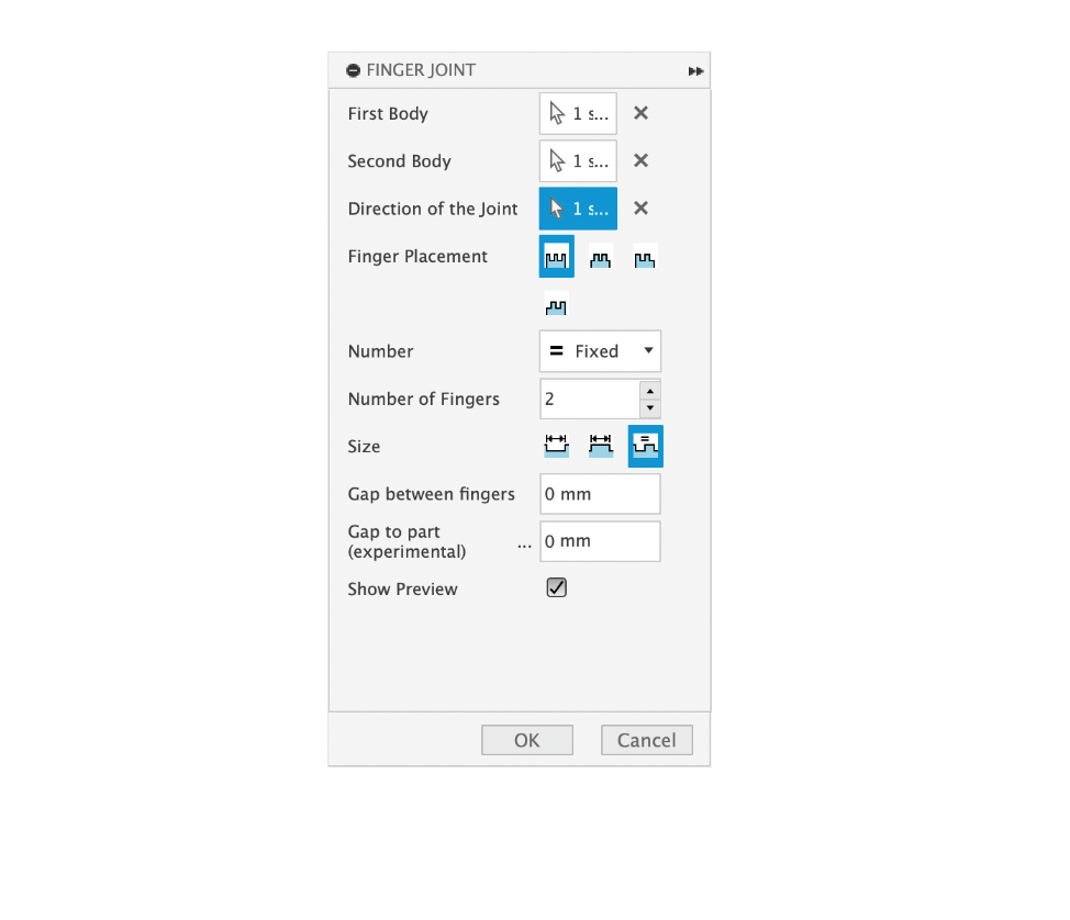
- Click on the Plug-in : Click on the "Finger Joint" plug-in, which should be under modify in the solid tab
- Select the bodies : Select the two bodies, and set the direction of joint to the edge of the finger joint you created on the triangle in part (4).
- Finger Settings : Set finger placement to outside, number to fixed (set to 2), size to equal notch and finger size, and gap between fingers to 0. (at AUBH, we will use Lightburn for lasercutting and will do kerf compensation to make sure we have a tight fit). At AUBH, your lasercutter kerf is 0.12mm.
- Click Ok : Click Ok to create the joints.
Checkoff 4
Show your finger joints to your instructorPart (8): Importing DXF Files
We need to add text to our calendar, so let’s import a DXF file.
Download DXF file from hereWhat is a DXF?
A DXF (Drawing Exchange Format) is a vector file format used for 2D designs, allowing you to import elements like text from software like Illustrator into Fusion360.
- Create Component: Go to Solid > Create > New Component > Set parent to Calendar Body.
- Create Sketch: Go to Sketch > Create Sketch > Select XY Plane.
- Click Insert → Insert DXF in Fusion360.
- Move the text to the desired position in the workspace by dragging it (here, move to X:-2.5mm, Y:-103mm)-- you may adjust this a bit in Illustrator later if it feels too close to the slider edge aesthetically
- Now, you’ve imported the text! You can always design in external software (like Illustrator) and bring it into Fusion360 as a DXF file to further manipulate-- this will be helpful later on if you want to add logos for 3D printing, for example.
Part (9): Projecting Sketch Entities (5 minutes)
Video Summary:
- Use the same sketch you imported the dxf into
- Click Create --> Project/Include --> Project Entities.
- Select the extruded calendar body (selection filter set as bodies). Set Projection Link to On.
- Click OK to complete.
- Create a construction line (mirror line): Make the construction line straight and in the middle of the projected calendar body (triangle should appear)
- Click on the Mirroring Tool: Click Create--> Sketch--> Mirror.
- Mirror the Rectnagular Slots: Select the rectangular bodies as the objects, and the mirror line as construction line creates in (5).
Part (10): 🚨Remixing🚨 (30 minutes)
Now it's time to “remix” this assignment by adding your own flair! Be creative and think about how you can personalize your design. If there's anything specific you want to create but aren't sure how, let us know so we can guide you!
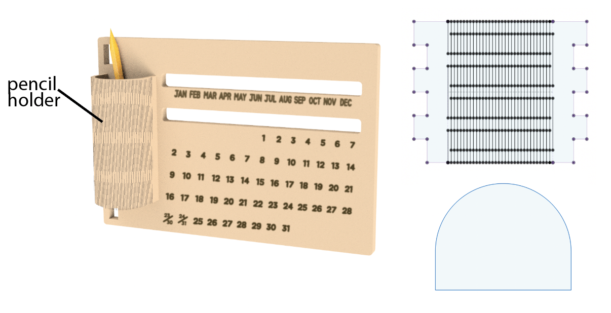
Living Hinges (Optional for Remix)
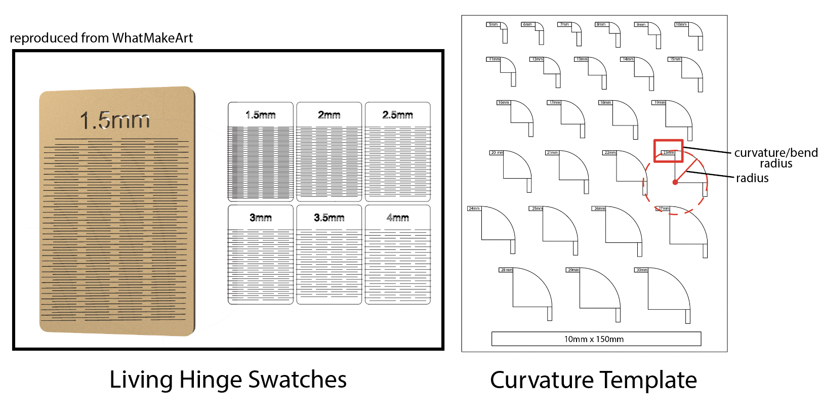 We encourage you to explore using living hinges in your remix (You will get a shout-out from your instructors if you do so!).
We have provided swatches for you on your tables,
and a curavture guide. Simply place the swatch on the curvature guide to understand what bend radii are compatible with
the swatch you want to CAD.
We encourage you to explore using living hinges in your remix (You will get a shout-out from your instructors if you do so!).
We have provided swatches for you on your tables,
and a curavture guide. Simply place the swatch on the curvature guide to understand what bend radii are compatible with
the swatch you want to CAD.
Below is a video on how you can make a living hinge with an example application.
Part (11): Exporting DXF file (5 minutes)
Note that the video says Part(7) although this is Part (11) for you-- this is because this video is from the Beginner Section.- Export the Sketch:
- Right-click on your sketch.
- Select Export as DXF.
- Open the DXF File:
- Open the exported DXF file in Adobe Illustrator (set the import to 1 unit = 1mm -- make sure units are in mm).
- Remove Construction Lines:
- Delete the lines that correspond to the construction lines included in the export.
Note: In future labs, we’ll demonstrate a method to export without including construction lines, which will streamline your workflow!
Part (12): Lasercutting (30 minutes)
For this part, please follow your instructors to D-Lab in order to lasercut; We will use Adobe Illustrator as our choice of Vector editing file that we can open our DXF in it, and interface with the lasercutter.
Your instructors will demonstrate to you what vector vs. raster files are, and how to set-up files for lasercutting. You may skip reading this section and just head to D-Lab. 😎
For your future reference, we will provide some insructions below on how to create an image for "vector cutting" vs. "rastering/engraving":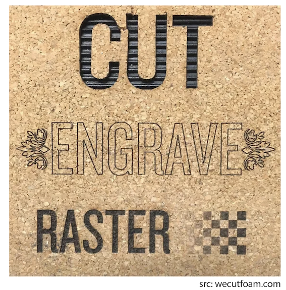
- Vector Cutting: The laser follows a path to cut through material (subtracts material).
- Engraving: The laser etches or marks the surface without cutting through (usually like an outline).
- Rastering: The laser scans and etches (no cutting) in a grid pattern to create detailed images or shading on the surface (great for photos and textures).
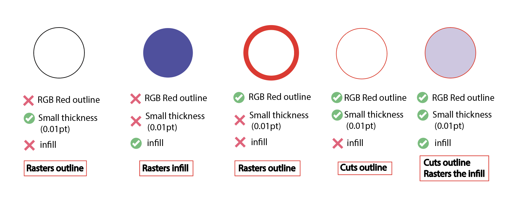
- Vector Cutting:
- 🔴 RGB red color (255, 0, 0)
- ⭕ Vector Shape (only outline, no infill)
- ✏️ outline line width (0.01pt)
- Raster Engraving: Anything that does not meet vector requirements
Part (13): Assemble the Calendar and Sand the Edges (30 minutes)
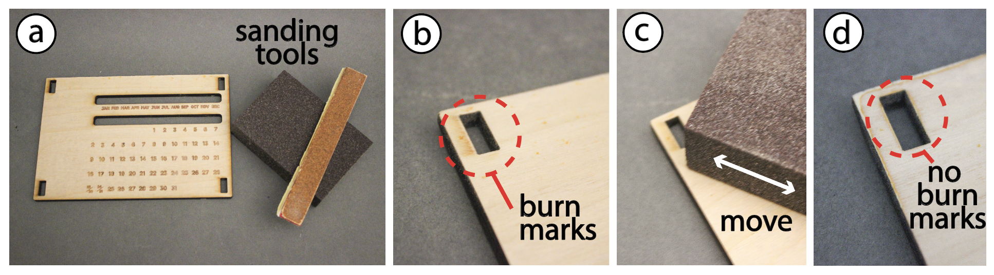
- Sanding Surface:
- Follow the visual instructions from the figure to sand off the burn marks on your piece.
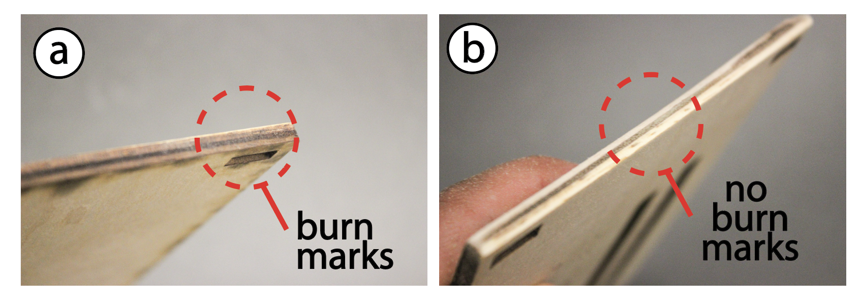
- Sanding Edges:
- Repeat the same process but with the edges
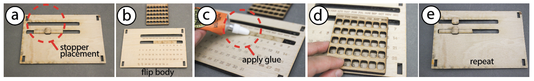
- Insert the Sliding Mechanism:
- Flip the calendar so that you are facing the back. Begin by inserting the long rectangular stopper component in the slot for the day of the month into its designated slot as shown in figure (a) (above).
- Glue the Stoppers:
- Flip the calendar so you are facing its front. Glue the day of the week slider and place it on top of the stopper(c-d). Make sure to hold in position until the glue sets (15 minutes dry time).
- Repeat:
- Repeat previous steps for the month slider.
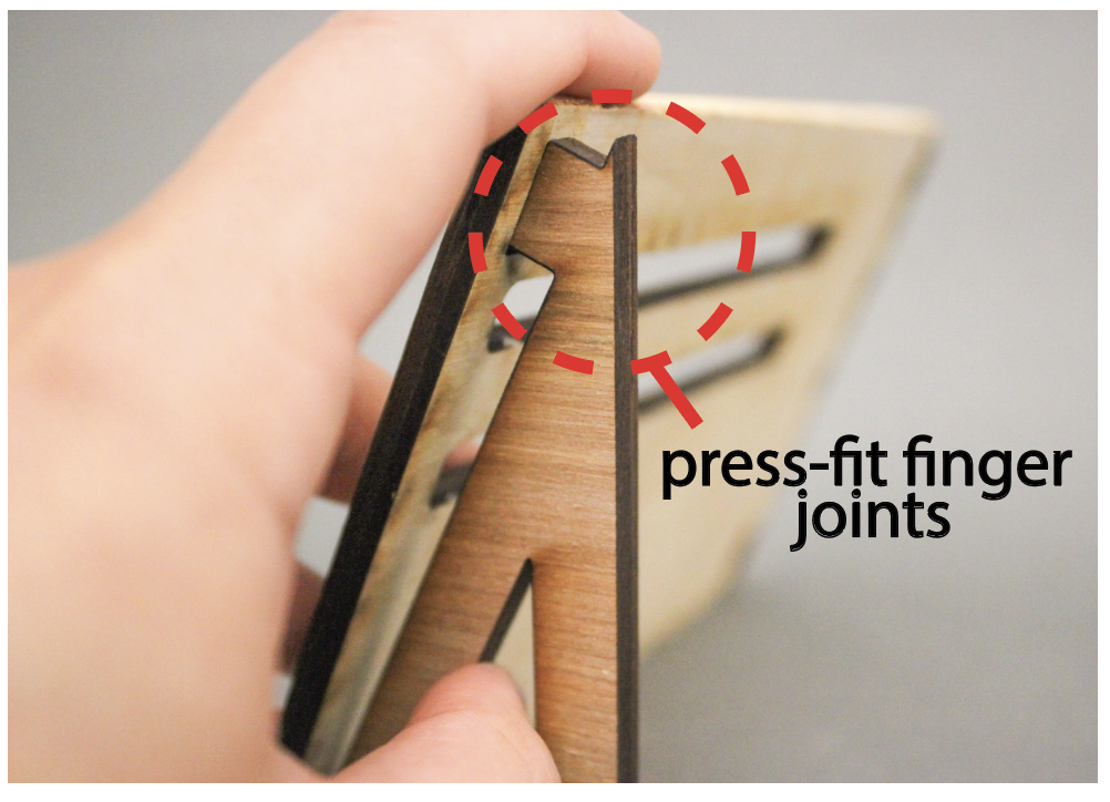
- Assemble the Legs :
- Once the glue has dried, press-fit the legs into their corresponding holes to secure them in place.
- Final Assembly:
- If you created any remix pieces, assemble those as well.
Congratulations, your dynamic calendar is ready! 🎉
Discussion & Reflections
- Discuss the advantages and limitations of using laser cutting for digital fabrication.
- What can we make? What is difficult to make?
- Reflect on the design process
- Consider any modifications that you would like to implement to improve/elevate your designed remix.
- Further Readings