Total Time: 2.5 hours
Quick Links
- Introduction & Safety
- Fabrication Quest
- Software & Hardware for the Lab
- Part (1): Variables & Equations
- Part (2): Sketching Parametrically
- Part (3): Extrusion
- Part (4): Threaded Holes
- Part (5): Sketching Revolve Profiles
- Part (6): Revolving
- Part (7): Extrude Cut
- Part (8): Understanding Sketch Constraints
- Part (9): Wrap and Emboss
- Part (10): Creating Blocks (REMIX)
- Part (11): Sweeping Corners
- Part (12): Assemblies in CAD
- Part (13): Materials & Colors
- Part (14): Rendering
- Part (15): Export and Share
- Part (16): FDM 3D Printing
- Part (17): SLA 3D Printing
- Discussion & Reflection
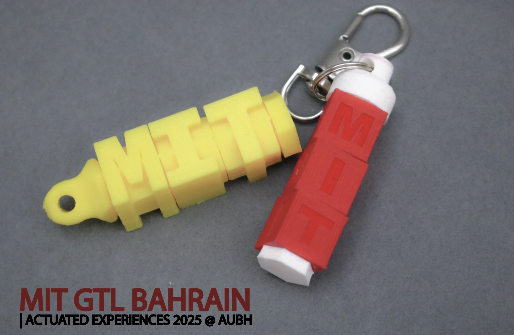
Lab 2: Let’s 3D Model a Rotating Keychain!
🦺 Introduction & Safety
(1 minute read)3D printing is an additive (add material) manufacturing process where computer-aided G-code (instruction code for the machine) is translated to build up material layer by layer. It has various techniques, including FDM , which extrudes hot thermoplastics (plastics that melt at elevated temperatures), SLA, which uses photoresin polymers that cure via light, and Polyjet 3D printing, among others.
In this lab, you will learn how to:- ✅ Learn advanced 3D modeling Techniques (Revolve, Sweep, Warp)
- ✅ Design for Multimaterial 3D Printing
- ✅ CAD a simple rotating element around a shaft
- ✅ CAD a threaded object
- ✅ Make a Mechanical Assembly
- ✅ Render a 3D Model in Fusion360
- ✅ Export files and prepare them for 3D printing
🔨 Fabrication Quest of the Day
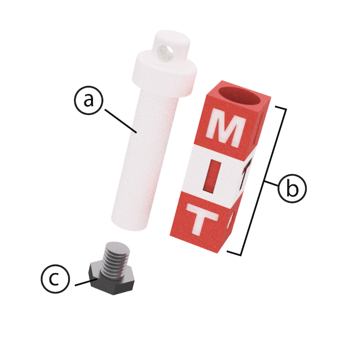
- Today, you will CAD 4-5 parts:
- (a) Threaded Shaft (x1)-- allows Remixing
- (b) Rotating Blocks (x3-4)-- allows Remixing
- Fabricated results will be for next lab, but you will put your files on the 3D printer today;
Your instructors will provide you with the following:- (c) The screw cap (x1), (Download Here)
🏗️ Software & Hardware
Software:
- Fusion360
- Ultimaker Cura (Ultimaker 3D Printer Slicing Program)
- Bambu Studio (Bambu 3D Printer Slicing Program)
- Photoworkshop for Anycube SLA Printer (SLA)
Machines (available for you):
- FDM 3D Printers (multi-material printing): Ultimaker S3, Bambu
- FDM 3D Printer (single material): Ultimaker, Prusa
- SLA(single material): Anycube
Materials (available for you):
Part (1): Creating Variables & Equations for Dynamic Dimensioning! (10 minutes)
Video Summary- Dimensioning models through variables allows for model dimension modification with ease
- To create dimension variables go to: Modify -> Change Parameters -> Add User Parameter (top "+" sign)
- Create a variable for “shaft_outer_d” representing the inner diameter of the Threaded Shaft, and set it to 9mm.
- Follow table below to add all the following variables, and one equation to your Fusion File Parameters. Don't forget to save as you go!
# Part Name (do not add to Fusion) Variable Name (add in Fusion) Expression Unit 2 Shaft Outer Diamter shaft_outer_d 9 mm 3 Shaft Length for 3 Rotating Blocks shaft_length_3b 36.2 mm 4 Shaft Length for 4 Rotating Blocks shaft_length_4b 48.2 mm 5 Shaft Threaded Hole Depth thread_depth 10 mm 7 Keychain Hole Diameter keychain_hole_d 4 mm 9 Rotating Block Size rot_b_size 12 mm 10 Rotating Block thickness rot_b_thick 12 mm 11 Rotating Block Hole Tolerance tolerance 0.6 mm 12 Rotating Block Hole Diameter rot_b_hole_d shaft_outer_d + tolerance mm
Part (2): Sketch and Dimension Parametrically (Sketching Keychain Shaft) (5 minutes)
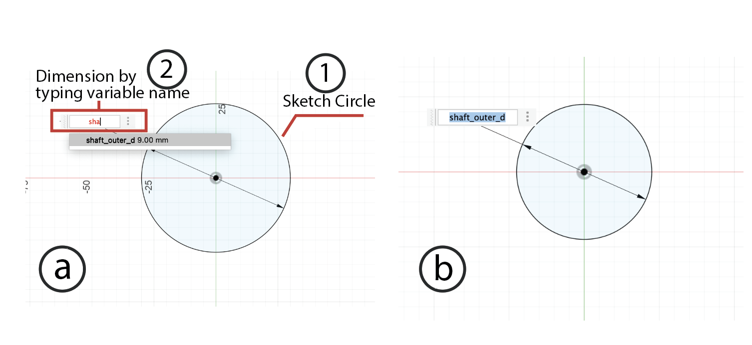
Instructions
- Draw a circle at the center (0,0).
- Dimension the first circle with “shaft_outer_d.”
- Exit Sketch, and rename the Sketch to "shaft-circle"
📍 If you need a refresher on how to sketch or dimension, please visit Lab 1 !
Part (3): Extruding the Sketch (give height to the shaft!) (5 minutes)
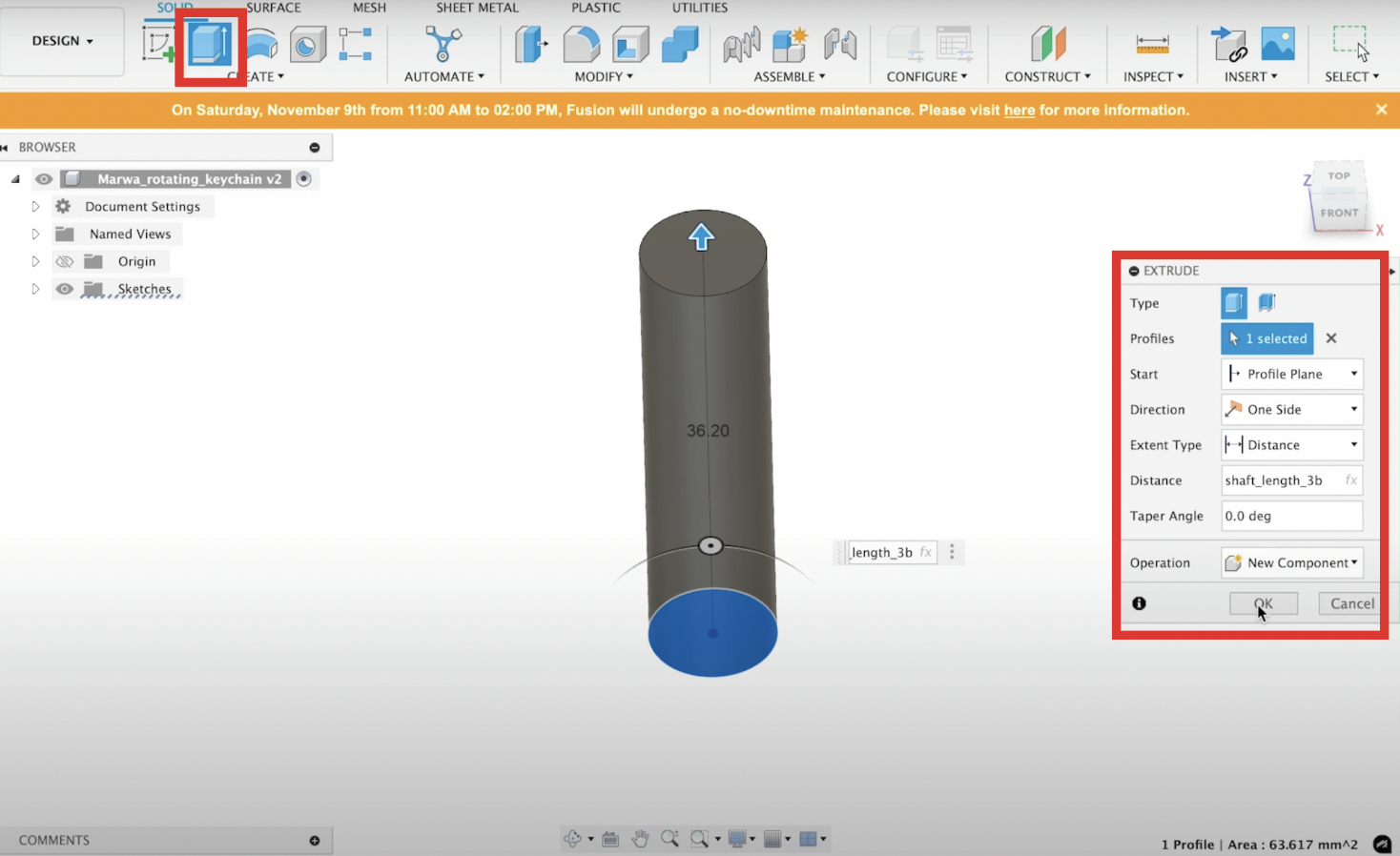
Steps:
- Click on Create.
- Select the Extrude Tool.
- Under Profile, select the area formed by the circle from your "shaft-circle" sketch.
- Set the Direction to One Side.
- Type the Distance as “shaft_length_3b” or "shaft_length_4b"-- here you must decide whether you will make a 3 block or 4 block keychain; No worries if you change your mind later on! 🤗
- Choose the operation as New Component. Why? For creating assemblies, it's best to use components.
- Click Ok to create the solid cylinder.
- Write click on the component and Rename it to "Shaft"
Part (4): Making a Threaded Hole (7 minutes)
Video Summary:- Toggle "Shaft-circle" sketch back on
- Go to Create.
- Select the "Hole" Tool.
- Under Face, select the top face of the cylinder.
- Set the Reference to the center of the circle sketch (i.e. the "point" at the circle's center from the sketch).
- Set the Hole Type to “Simple”
- Set the Hole Tap Type to “Tapped”
- Set the Thread Offset to “Full”
- Set the Drill Point to “Angle”
- Set the Depth to "thread_depth"
- Set the Size to 7mm
- Set the Designation to M7mmx1mm
- Have Modeled checked ON
- Click Ok to create your threaded hole.
Checkoff 2
Show your shaft with its threaded hole to your instructor, and explain to them what M7mmx1mm means (you are encouraged to look up the answer online 👀)!
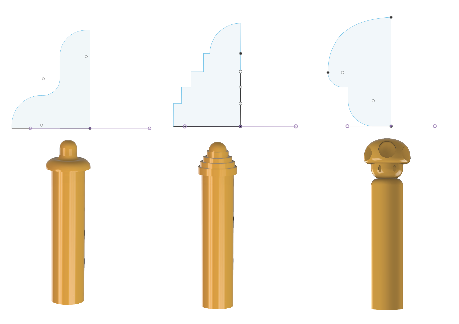
Part (5): Creating Profile of Keychain Holder Head (🚨REMIX OPTIONAL🚨) (20 minutes)
-
Create an Axis Through the Cylinder:
- Go to the Construct command in the top menu.
- Select Axis Through Cylinder.
- Click on the cylinder to establish the axis of rotation.
-
Create a Plane at an Angle to the Axis:
- Again, in the Construct menu, select Plane at Angle.
- Click on the axis you created.
- Enter the angle as "0" for the plane, then confirm.
-
Use the Plane to Sketch the profile for the Top Holder on [🚨 REMIX OPPORTUNITY🚨]:
- On the new plane, right click on it and select Create New Sketch (there are other ways of doing this, but we opt for right clicking on plane for now).
- To ensure we remain within bounds, go to Create, then Project, Select Entity (Selection Filter) and click on the perimeter of the top circle of the cylinder for Geometry. Kepp Projection Link on.
- Your Design Constraints for your REMIX are as follows:
- Draw the profile you would be revolving for the top holder on this plane. Recall that this should be symmetric and should not extrude out too much. Make sure that the profile is closed!
- Once done, click Finish Sketch
In the next step, we will revolve this profile to create a symmetric top keychain holder.
Checkoff 3
Show & explain your sketched profile to your instructor ensuring that your design meets Remix Design Constraints!
Part (6): Revolving Radially Symmetric Geometry(5 minutes)
Video Summary:- Revolve Command: Go to Create > Revolve in the toolbar.
- Select Profile: Click on the profile (the closed shape) that you want to revolve.
- Select Axis: Click the axis of symmetry (the cyliner axis we constructed) around which the profile will revolve.
- Set Angle: In the Revolve dialog, set the angle to 360° (or the desired angle for partial revolution if you want to play around with this!).
- OK: Click OK to complete the operation.
Part (7): Making Hole for Keychain (5 minutes)
- Create a Tangent Plane: Create a plane that is tangent to the surface of your revolved part using Construct > Tangent Plane.
- Sketch a Circle on the Tangent Plane: Start a sketch on the tangent plane and draw a circle where you want the hole.
- Dimension the Circle: Use the Dimension tool to set the circle's diameter to 4mm (or your desired size).
- Extrude Cut the Hole: Use Create > Extrude, select the circle, and set it to Cut with the Symmetric direction to cut both sides of the part.
- Finish: Click OK to complete the hole creation process.
Checkoff 5: Pick your 3D Printing Fabrication Method
Let your Instructor Know which 3D printing method you would like to use. We have a spreadsheet to coordinate printing, and this will also affect what colors you would use.
Part (8): Understanding Sketch Relationships & Constraints (5 minutes)
Part (9) [OPTIONAL]: Wrapping/Embossing a Design on your cylindrical shaft (5 minutes)
- Profile: Select the sketch you want to emboss.
- Face: Select the curved or flat surface you want to emboss onto.
- Emboss Type: Choose between Emboss/add (to raise) or Deboss/cut (to lower).
- Depth: Set the desired height or depth of the emboss.
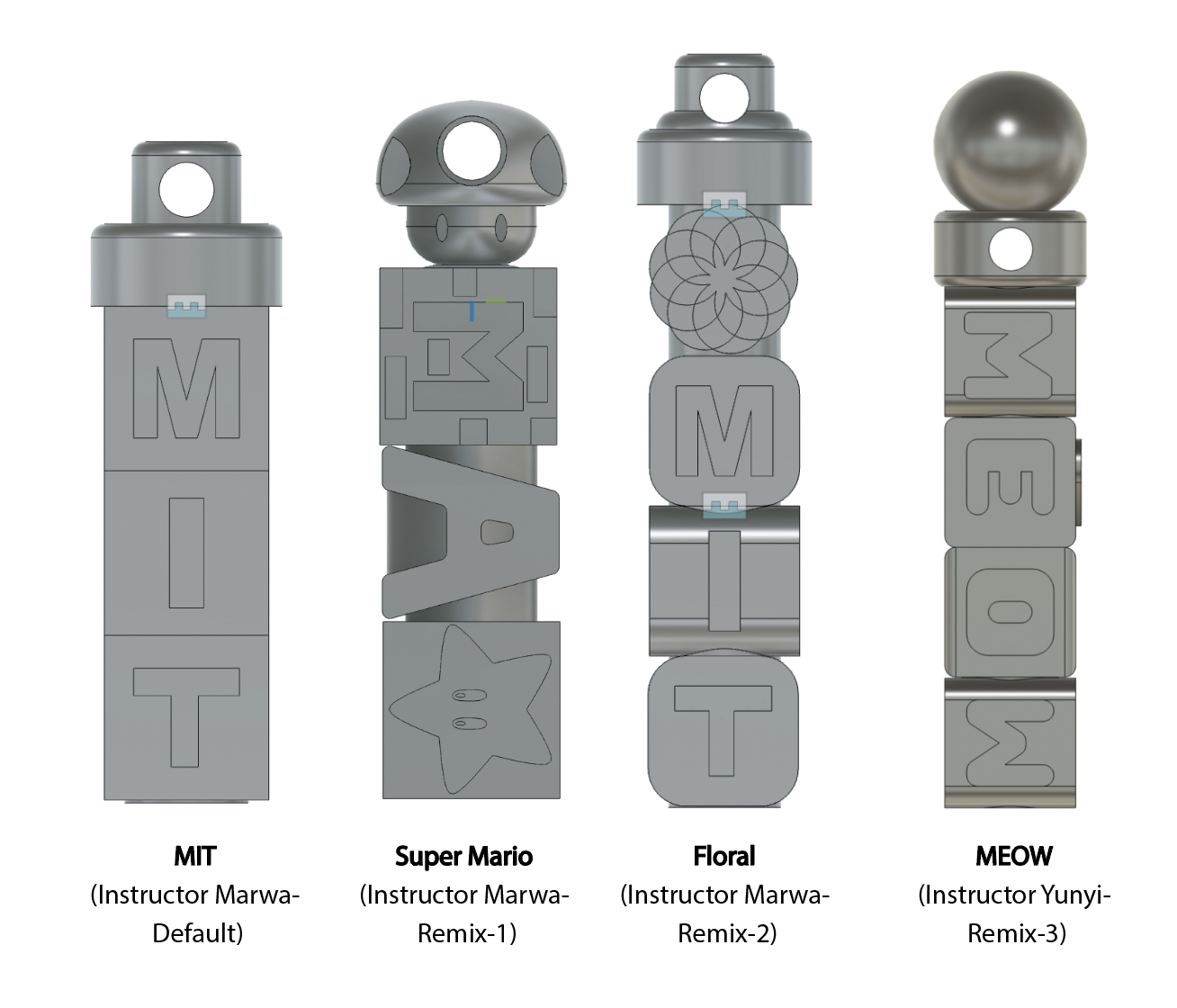
Part (10): Creating Blocks (🚨REMIX🚨) (30 minutes)
Note that the video says Part(9) although this is Part (10) for you-- this is because this video is from the Beginner Section. As you create you BLOCKS we recommend creating them as "New Components" even though video shows Bodies
Now is the time to be as ✨creative✨ as you'd like! Create your keychain blocks by following the design guidelines outlined below, and refer to the video to guide through some steps to understand those guidelins. Note that although the video says "Part-9", this is "Part-10" for you;
Below are some of your instructor's creations-- you might also consider designing something in illustrator and importing as DXF (like what you learned in Lab 1), and as demonstrated in the video!
 Design Constraints Summary:
- Block Size: 12mm (variable: rot_b_size)
- Hole Size: 9.6mm (variable: rot_b_hole_d)
- General 3D Printing Guidelines: Link1, Link2
- Minimum Feature size: 2x Nozzle diameter (e.g. 0.8mm for 0.4mm Nozzle)
- Angles (for minumum support material): < 50 Degrees
Part (11) [OPTIONAL]:Sweeping for Aesthetic Corners (5 minutes)
Note that the video says Part(13) although this is Part (11) for you-- this is because this video is from the Beginner Section.
- Construct a plane along the circular hole path (ensure the sketch is toggled on).
- Sketch a circle with a diameter of approximately 2mm.
- Click on Create and select Sweep.
Part (12): Assemblies in CAD (10 minutes)
Note that the video says Part(11) although this is Part (12) for you-- this is because this video is from the Beginner Section.-
Ensure Blocks Are Components:
- Convert blocks to components by right-clicking and selecting "Convert to Component".
-
Create Assembly:
- Click "Assemble" "Joint".
- Choose the Shaft as Component 1 and the first Block as Component 2.
- Define the joint type as "Simple" and "Revolute" .
-
Add Remaining Blocks:
- Apply "Joint" again from the previous steps.
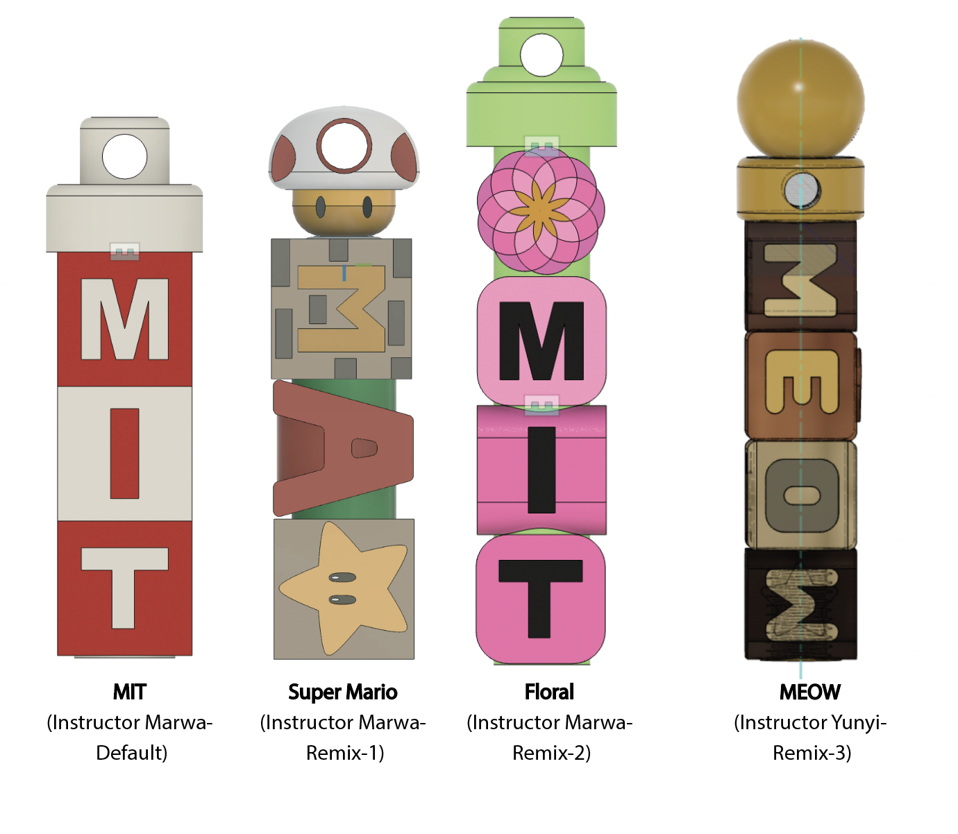
Part (13): Assigning Materials & Colors (10 minutes)
Note that the video says Part(10) although this is Part (13) for you-- this is because this video is from the Beginner Section.
Below are examples from some of your instructor's--
-
Assign Material:
- Right-click the body/component in the Browser and select "Appearance".
- Drag a material from the Appearance panel to the body (whole body or specific faces).
- Custom Color (Tutorial-Link):
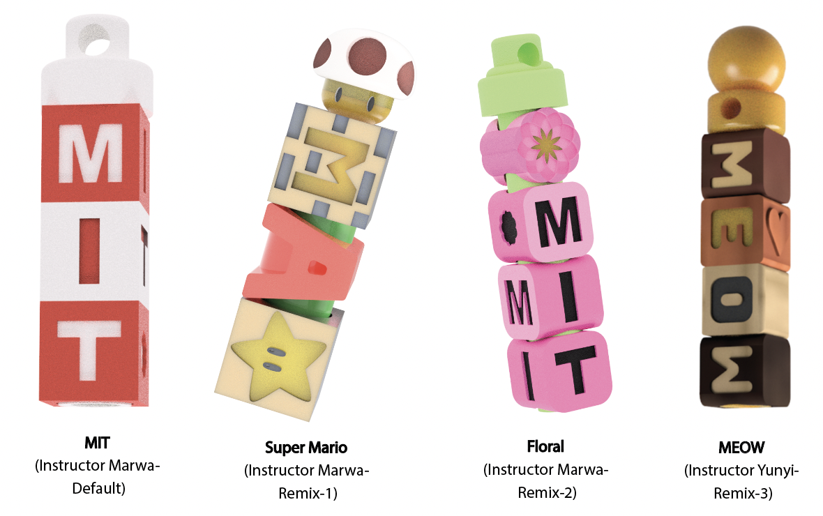
Part (14): Rendering (5 minutes)
Note that the video says Part(12) although this is Part (14) for you-- this is because this video is from the Beginner Section.
Below are examples from some of your instructor's--
-
Switch to Render Workspace:
- Click on the Design tab and switch to the Render workspace.
-
Adjust Scene Settings:
- Click on Scene Settings to adjust the lighting and background to your liking.
-
Render and Save Image:
- Click on In-Canvas Render to generate the render.
- Once done, save the image to your computer.
- Upload Render image to Lab-2 Drive Folder under the name "LastName_FirstName_keychain"
Part (15): Export STL Files & Share Fusion Project (10 minutes)
Note that the video says Part(13) although this is Part (15) for you-- this is because this video is from the Beginner Section. We would like to export each part individually. To do so:- Go to the hierarchy in Fusion 360, right-click on the component or body, and click Export.
- Select the file type as STL and save it locally. Use the naming convention: "LastName_FirstName_Number" (e.g., Jane_Doe_1).
- Repeat the same steps for all components you have.
- Upload all STL files to the following Google Drive Link.
-
Share the link to your Fusion 360 file so your instructors can access and edit your files if necessary. To do this:
- Open your project in Fusion 360.
- Click on the File menu and select Share > Share File Link.
- Enable the option to allow downloading
- Copy the generated link and put it in this spreadsheet next to your name.
Below are options based on what you pick: (1) FDM 3D Printing (2) STL Printing
Part (16-A): Directly Export for 3D Printing (FDM)
-
Export the 3D Model:
- Click File in the top-left corner, then select 3D Print.
-
Use the 3D Print Utility:
- Click on 3D Print from Utility.
- Choose Application Custom, and then load CURA from your applications list.
-
Open in Cura:
- After selecting your model, click OK.
- CURA will open automatically with the selected model.
-
Export Each Component:
- Repeat the process for each component to export them one by one.
Part (16-B): Setting up File for Multi-material 3D Printing (FDM)
Consult with your instructor to show you how this is done
Part (16-C): Setting Up Print Parameters
-
Adjust Model Orientation:
- Ensure your models are in the correct orientation.
- Use Rotate and Move tools to adjust the position if needed.
- Make sure models do not overlap.
-
Adjust 3D Printing Settings:
- Set Layer Thickness to 0.1mm (fine quality, for threading).
- Set Speed to 100mm/s.
- Set Fill Density to 15%.
- Enable Support (set to "only touching the print bed").
- Disable Build Plate Adhesion (usually recommend to use brim, but here we just don't want to affect your design).
-
Slicing and Preview:
- Click Slice to generate the G-code.
- Click Preview to check your print setup before exporting.
Part (17-A): Setting Up Print parameters and Setup for SLA Printing
Consult with your instructor to set-up your file
Discussion & Reflections
- Discuss the advantages and limitations of using 3D Printing for digital fabrication.
- What can we make? What is difficult to make?
- Reflect on the design process
- Consider any modifications that could have improved/elevated youre remix design.